
User's Manual
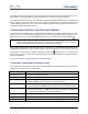
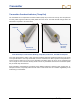
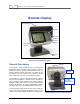
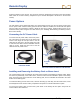
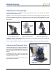
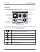
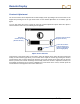
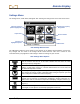
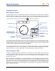
Table Of Contents
- This device complies with Part 15 of the Rules of the FCC. Operation is subject to the following two conditions: (1) this device may not cause harmful interference, and (2) this device must accept any interference received, including interference tha...
- Safety Precautions and Warnings
- Dear Customer:
- Introduction
- Receiver
- Transmitter
- Remote Display
- Battery Charger
- Locating
- The Target Steering Function
- Appendix A: System Specifications and Maintenance Requirements
- Appendix B: Projected Depth Versus Actual Depth and the Fore/Aft Offset
- Appendix C: Calculating Depth Based on Distance Between FLP and RLP
- Appendix D: Reference Tables
- Appendix E: EU Required Documentation
- LIMITED WARRANTY

Transmitter
DigiTrak
®
F2
®
Operator’s Manual 41
The transmitter must fit snugly in the housing. It may be necessary to wrap the transmitter with tape or O-
rings and/or use a housing adapter for larger drill housings. Contact DCI for more information.
The index slot in the front end cap of the transmitter should fit onto the anti-roll pin (key) in the housing for
proper alignment of the transmitter in the housing. When the drill head’s 12 o’clock position does not
match that of the transmitter, use the receiver’s roll offset function to display appropriate roll values. See
“Roll Offset Menu” in the Receiver section.
Temperature Updates and Overheat Indicator
F2 transmitters are equipped with an internal digital thermometer. The internal temperature of the trans-
mitter is sent to the receiver and remote display every 4.4 seconds. This temperature is displayed on the
bottom right of the receiver and remote display screens next to the transmitter temperature symbol
.
NOTE: Because the digital thermometer is inside the transmitter, temperature increases due to
external drilling conditions will take time to transfer to the transmitter. Any increase in
temperature should be dealt with quickly to avoid irreversible damage.
Normal drilling temperatures range from 64°F (16°C) to 104°F (40°C). You should suspend drilling when
temperatures exceed 95°F (35°C) to permit cooling. Once the temperature reaches 118°F (48°C) the
thermometer icon will change to display steam and it will flash:
. At this point, the transmitter has
become dangerously hot and must be cooled immediately or it will be damaged. The transmitter will shut
down at 176°F (80°C).
To cool the transmitter, stop drilling and/or add more drilling fluid.
Transmitter Temperature Warning Tones
The audible tones emitted by the F2 receiver and remote display to indicate increases in the transmitter
temperature are summarized in the table below.
Temperature Warning Tones
Below 61°F (16°C) No tones for temperature increases.
61–97°F (16–36°C) Double-beep sequence (beep-beep) for every 4°C increase in temperature.
104–111°F (40–44°C) Two double-beep sequences (beep-beep, beep-beep) for every 4°C increase in
temperature. NOTE: Action is required to cool the transmitter.
118–133°F (48–56°C) Three double-beep sequences (beep-beep, beep-beep, beep-beep) for every 4°C
increase in temperature. NOTE: Cooling is critical to avoid irreversible damage.
Above 140°F (60°C) Three double-beep sequences every 5 seconds on the remote display, and every
20 seconds on the receiver. NOTE: Warning signifies dangerous drilling condi-
tions; irreversible damage may have already been done.
Above 176°F (80°C) Transmitter shuts down.
180°F (82°C) FS and FC transmitter overheat indicator (temp dot) turns black (see below).
220°F (104°C) FX and FXL transmitter overheat indicator (temp dot) turns black (see below).