
User's Manual
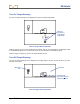
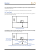
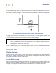
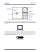
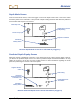

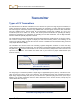
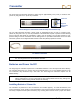
Table Of Contents
- This device complies with Part 15 of the Rules of the FCC. Operation is subject to the following two conditions: (1) this device may not cause harmful interference, and (2) this device must accept any interference received, including interference tha...
- Safety Precautions and Warnings
- Dear Customer:
- Introduction
- Receiver
- Transmitter
- Remote Display
- Battery Charger
- Locating
- The Target Steering Function
- Appendix A: System Specifications and Maintenance Requirements
- Appendix B: Projected Depth Versus Actual Depth and the Fore/Aft Offset
- Appendix C: Calculating Depth Based on Distance Between FLP and RLP
- Appendix D: Reference Tables
- Appendix E: EU Required Documentation
- LIMITED WARRANTY

Receiver
34 DigiTrak
®
F2
®
Operator’s Manual
Receiver Locate Mode Screen with Transmitter in Range (Trigger Out)
When the roll offset function is used (an electronic compensation to match the transmitter’s 12 o’clock
position to the drill head’s 12 o’clock position), the roll indicator will have a hollow dot and the letters RO
for roll offset at the bottom right, as shown here. For more information on the roll offset, see
“Roll Offset
Menu” above.
Roll Offset Is Activated
The roll/pitch update meter displays the quantity of roll/pitch data being received from the transmitter.
When the meter is empty, no roll/pitch data is being received, and all information will disappear on both
the receiver and remote display. Depth and predicted depth readings may still be taken, but the receiver
will assume the transmitter has a pitch of zero, as indicated by the following image appearing on the
depth or predicted depth mode screen.
Pitch Assumed Zero
2
Locating Target
(FLP or RLP)
Transmitter Signal
Strength
Roll/Pitch
Update Meter
Roll Indicator
Transmitter
Temperature
Transmitter Pitch
Receiver
+