
User's Manual
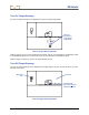
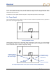
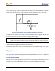
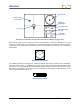

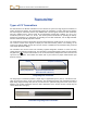
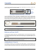
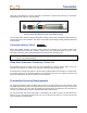
Table Of Contents
- This device complies with Part 15 of the Rules of the FCC. Operation is subject to the following two conditions: (1) this device may not cause harmful interference, and (2) this device must accept any interference received, including interference tha...
- Safety Precautions and Warnings
- Dear Customer:
- Introduction
- Receiver
- Transmitter
- Remote Display
- Battery Charger
- Locating
- The Target Steering Function
- Appendix A: System Specifications and Maintenance Requirements
- Appendix B: Projected Depth Versus Actual Depth and the Fore/Aft Offset
- Appendix C: Calculating Depth Based on Distance Between FLP and RLP
- Appendix D: Reference Tables
- Appendix E: EU Required Documentation
- LIMITED WARRANTY

Receiver
DigiTrak
®
F2
®
Operator’s Manual 33
In this example, the line under the number 2 indicates that the ft/m setting is highlighted. To change this
setting, hold in the trigger until a box appears around the number 2, as shown below. Once you see the
box, click the trigger to increase (in 1-ft or 1-m increments) to the desired number. Once you reach the
desired number, hold in the trigger, and the box will turn back into an underline under the ft/m setting.
Set Target Depth Value Screen (Foot or Meter Setting Selected)
To change the in./cm setting, click the trigger to move the underline to the in./cm position, and then hold
the trigger in until a box surrounds the number. Once you see the box, click the trigger to increase in 1-in.
or 2-cm increments. Once you have the desired in./cm setting, hold in the trigger.
NOTE: If you click past 11 in. or 98 cm, then the number in the ft/m setting will automatically increase.
Also, if you click past your desired value, you can either click through the maximum values (99 ft
or 30 m), or wait about 10 seconds to exit the menu and then reenter the Target Steering menu,
to start back at the default value (2 ft or 0.50 m).
To set the displayed value as your target depth, click the trigger to move the underline underneath the
checkmark and hold the trigger in. A confirmation signal will sound.
For information about how to position the receiver ahead of the tool for target steering, see the Target
Steering Function section.
Display Screens
The basic receiver displays include the locate mode screen, the depth mode screen, and the predicted
depth screen. These are presented below. For more information regarding these screens and for detailed
locating instructions, please see the Locating section.
Locate Mode Screen
When the receiver is detecting a signal from a transmitter, the locate mode screen provides real-time data
about the transmitter’s location, temperature, pitch, roll, and signal strength. The roll/pitch meter shows
the quality of the signal from the transmitter. The locate mode screen is the default screen setting.