
User's Manual
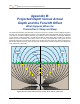
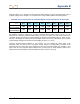

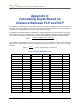


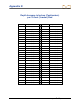
Table Of Contents
- Safety Precautions and Warnings
- Dear Customer:
- Introduction
- F Series Battery Charger System
- Receiver
- General Description
- Standard Receiver Display Screen Symbols
- /Power On
- Power Off
- Automatic Shutdown
- Toggle & Trigger Switches
- Audible Tones
- Main Menu
- /Calibration Menu
- /Height-Above-Ground (HAG) Menu
- /Settings Menu
- Transmitter Selection Menu
- /DigiTrak LWD (Log While Drilling) Menus
- Target Steering Menu
- Using the Keypad
- Display Screens
- Transmitter
- Remote Display
- Locating
- The Target Steering Function
- Appendix A: System Specifications and Maintenance Requirements
- Appendix B: Projected Depth Versus Actual Depth and the Fore/Aft Offset
- Appendix C: Calculating Depth Based on Distance Between FLP and RLP
- Appendix D: Reference Tables
- Appendix E: EU Required Documentation
- LIMITED WARRANTY

DIGITAL CONTROL INCORPORATED
DigiTrak
®
F5
®
Operator’s Manual 81
Appendix B:
Projected Depth Versus Actual
Depth and the Fore/Aft Offset
What Happens When the
Transmitter Is Steep and Deep
The signal field emitted by the transmitter, as shown in Figure B1, consists of a set of elliptical signals or
flux lines. The flux lines indicate the position of the transmitter. When the transmitter is level with respect
to the ground, you will find that the locate line (LL) is directly over the transmitter, and the depth displayed
on the receiver is the actual depth. You will also find that the locate points (FLP and RLP) are at equal
distances from the transmitter. The location of the LL is found at the intersection of the ground and the
horizontal component of the flux field, and the FLP and RLP are found where the vertical components of
the flux field intersect with the ground. Some of the horizontal and vertical components are identified by
short yellow lines in Figure B1.
Figure B1. Flux Field and Geometry of FLP, RLP, and LL (side view)
RLP
FLP
LL