
User's Manual
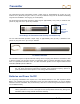
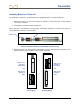
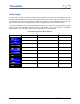
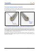
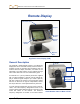
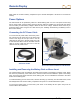
Table Of Contents
- Safety Precautions and Warnings
- Dear Customer:
- Introduction
- F Series Battery Charger System
- Receiver
- General Description
- Standard Receiver Display Screen Symbols
- /Power On
- Power Off
- Automatic Shutdown
- Toggle & Trigger Switches
- Audible Tones
- Main Menu
- /Calibration Menu
- /Height-Above-Ground (HAG) Menu
- /Settings Menu
- Transmitter Selection Menu
- /DigiTrak LWD (Log While Drilling) Menus
- Target Steering Menu
- Using the Keypad
- Display Screens
- Transmitter
- Remote Display
- Locating
- The Target Steering Function
- Appendix A: System Specifications and Maintenance Requirements
- Appendix B: Projected Depth Versus Actual Depth and the Fore/Aft Offset
- Appendix C: Calculating Depth Based on Distance Between FLP and RLP
- Appendix D: Reference Tables
- Appendix E: EU Required Documentation
- LIMITED WARRANTY

DIGITAL CONTROL INCORPORATED
DigiTrak
®
F5
®
Operator’s Manual 41
Transmitter
Types of F5 Transmitters
DCI manufactures several different transmitters with a total of five frequency options (1.3 kHz, 8.4 kHz, 12
kHz, 18.5 kHz, 19.2 kHz) for use with the F5 system. All F Series and F5 transmitters provide pitch
readings in 0.1% or 0.1° increments (from 0% to 100% or 0° to 45°). This section presents information for
operating the battery-powered F Series and F5 transmitters. For information on operating the FC cable
transmitter, see the DigiTrak Multi-Function Cable Box (MFCB) Operator's Manual.
The transmitter fits inside the drill housing and emits electromagnetic signals of a particular frequency.
The F5 receiver must be programmed to detect the specific frequency of the transmitter. See “Verifying
Signal” later in this section the “Transmitter Selection Menu” in the Receiver section for more information.
Be sure the receiver is calibrated to the transmitter being used and verify depth data before drilling.
The transmitter and receiver must have matching regional designation numbers to ensure that they can
communicate and comply with local operating requirements. The transmitter’s regional designation
number is located inside the globe icon (
) near the serial number on long-range and extended long-
range transmitter battery compartments and on the front end cap of the short-range transmitter. This
number must match that of your receiver for proper communication (see Receiver section).
Long-Range FX Transmitter
The long-range F5 and F Series transmitters all measure 15 in. (38.1 cm) long and 1.25 in. (3.175 cm) in
diameter and have a depth range of approximately 65 ft (19.8 m).
Options for the long-range transmitter include the FX in 12 kHz (grey) or 19 kHz (black), the 5XD 12/1.3
(blue) which operates in dual-mode at 12 kHz and 1.3 kHz (reduced signal strength in this mode) or in
single mode at 12 kHz, the 5XD 19/12 (blue) which operates at either 12 kHz or 19 kHz, the 8.4 kHz
model 5X 8.4 (blue), and the 18.5 kHz model 5XD 18.5 (blue).
Extended Long-Range FXL Transmitter
Transmitter Serial
Number
Regional Designation Number
(Must Match that of Receiver)
Battery Compartment
Front End Cap with
Temp Dot and Index Slot