
User's Manual
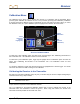
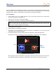
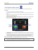
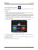
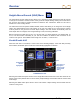
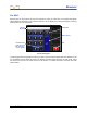
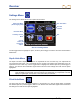
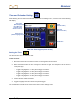
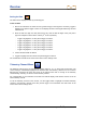
Table Of Contents
- Safety Precautions and Warnings
- Dear Customer:
- Introduction
- F Series Battery Charger System
- Receiver
- General Description
- Standard Receiver Display Screen Symbols
- /Power On
- Power Off
- Automatic Shutdown
- Toggle & Trigger Switches
- Audible Tones
- Main Menu
- /Calibration Menu
- /Height-Above-Ground (HAG) Menu
- /Settings Menu
- Transmitter Selection Menu
- /DigiTrak LWD (Log While Drilling) Menus
- Target Steering Menu
- Using the Keypad
- Display Screens
- Transmitter
- Remote Display
- Locating
- The Target Steering Function
- Appendix A: System Specifications and Maintenance Requirements
- Appendix B: Projected Depth Versus Actual Depth and the Fore/Aft Offset
- Appendix C: Calculating Depth Based on Distance Between FLP and RLP
- Appendix D: Reference Tables
- Appendix E: EU Required Documentation
- LIMITED WARRANTY

Receiver
DigiTrak
®
F5
®
Operator’s Manual 23
1-Point Calibration (Above Ground)
The 1-point calibration is the preferred calibration method. It requires the drill head be above ground.
To calibrate:
1. The receiver must be parallel to and level with the transmitter.
2. The transmitter must be on and in its housing. It is preferable to conduct the procedure on level
ground.
3. Measure 10 ft (3 m) from the center of the transmitter to the inside edge of the receiver as shown
below in the 1 point calibration screen.
4. Verify that roll and pitch values are being displayed on the receiver and that a steady signal is
being received from the transmitter.
5. Select the 1 point calibration option from the main menu. The following screen will display.
1 Point Calibration Screen
6. Click the trigger to initiate the calibration or toggle right and select the exit option to be returned to
the main menu.
7. After the checkmark is selected, the screen will show that the receiver is calibrating. Do not move
the receiver. Four short tones and a check mark on the screen indicate a successful calibration.
Two long tones indicate a failure, verify the setup and try again or contact DCI for support.
After a successful calibration, take a depth measurement with the transmitter and receiver in the same
orientation as during calibration. The depth should be 10 ft ± 5 in. (or 3 m ± 15 cm).
NOTE: It may be necessary to obtain a “reference lock” on a locate point before the depth data will
display. See the locating section for more information on obtaining a reference lock.
Accept 1 Pt
Calibration
(Shown
Highlighted)
Exit
(Cancels
Calibration)