
User's Manual

VuLink Operation & Installation Guide 860‐00198‐00 REV E
DigitalAlly,Inc.|InstallationInstructions 2‐2
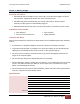
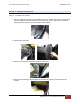
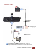
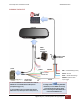
Step 2: Power, Ignition, and Ground Connections
Remove 6 to 7 inches of the outer jacket at the bare end of the base cable.
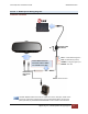
The Red wire of the base cable should be connected to the vehicle constant
+12VDC through the supplied fuse kit. Connect the Blue wire to the ignition
switch where +12VDC is only present when the vehicle ignition key is in the
ON position. The Black wire connects directly to the vehicle’s chassis.
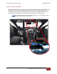
Secure all cables and in-line fuse housing using Velcro or standard tie
wraps as required. Consult Figure 3-2 below.
To ensure stable operation, power and ground should be directly connected to
the vehicle battery.
Step 3: VuLink Trigger Connections
Consult the Section 3 diagrams for your specific video system or generic input trigger
connection. VuLink has two input trigger options for you to choose from.
If installing VuLink to be used only with MicroVu HD, do not connect the
VuLink trigger wires. The MicroVu HD triggers are used instead.
The Orange wire is an active high trigger input which is tied to a switched +12VDC source when
the desired trigger is active. This wire is usually tied to the emergency light bar controller output.
The Brown wire is an active low trigger input which is tied to a switched 0VDC source when the
desired trigger is active. This wire is used with the DVM-800 and DVM-250Plus and is typically
tied to the IF box output alarm. The wire is the VuLink output trigger. When you press
the record button on your FirstVu HD, VuLink will apply a 1 second +12VDC signal on this wire.
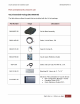
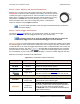
Make the connections as shown in the table below:
Wire Color Function Connection
RED
Battery Connect to +12VDC battery terminal (Use Fuse kit)
BLACK
Ground Connect to vehicle chassis ground
BLUE
Ignition Connect to +12VDC switched ignition
Trigger OUT
Consult the diagrams in Section 4 for your installation.
This wire connects to the video system input sensor.
Choose one of the two input trigger options below
BROWN
Trigger IN
Active LOW
For the DVM-250, connect to BROWN wire of I/F box.
Optional GND (active LOW) trigger.
ORANGE
Trigger IN
Active HIGH
For DVM-100/400/250Plus/440Ultra/500Plus/750,
connect to +12VDC when the emergency light bar is
active (or any other desired +12VDC trigger).
For DVM-800 connect to DWM Wireless Microphone
Trigger Output (Green).
Figure 3-2: VuLink Base Cable Connections