
User's Manual

VuLink Operation & Installation Guide 860‐00198‐00 REV E
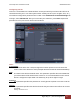
DigitalAlly,Inc.|Model‐SpecificWiringDiagrams 3‐5
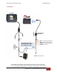
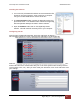
DVM-250Plus or DVM250 (with interface box)
RED=+12VDCBattery (Fused)
BLACK=ChassisGround
BLUE=+12VDCSw.Ignition
ORANGE=Optional+12VDC
inputtrigger
VuLinkBaseCable
008‐01456‐00
DVM
I/FBox
1. ConnectBROWNwirefromVuLinkBaseCableto
BROWNwireofI/Fboxinputsensorcable(output
alarm)
2. ConnectWHITEwirefromVuLinkBaseCableto
WHITEwireofI/Fboxinputsensorcable(Sensor5)
NC
BROWN
WHITE
I/FBoxInput
SensorCable