
User's Manual

VuLink Operation & Installation Guide 860‐00198‐00 REV E
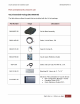
DigitalAlly,Inc.|Model‐SpecificWiringDiagrams 3‐3
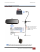
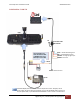
DVM-800 / DVM-LiVE
I/FBox
VuLinkBaseCable
008‐01456‐00
RED=+12VDCBattery (Fused)
BLACK=Ground
BLUE=+12VDCSwitchedIgn
BROWN=OptionalGND
InputTrigger
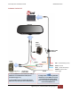
DVM‐800
NC
ORANGE
1.ConnectORANGEwirefromVuLinkBaseCableto
GREENwireoftheDWMWirelessMicrophone
(microphonetriggerout)
2.ConnectWHITEwirefromVuLinkBaseCableto
WHITEwireofI/Fboxinputsensorcable(Sensor5)
I/FBoxInput
SensorCable
WHITE
‐‐‐DONOTCONNECT
THISGREENWIRE
IfaddingVuLinktoanexistingDVM‐800
Installation,cuttheGREENwirecoming
fromtheI/FBoxInputSensorCable
beforeconnectingtheDWMGREENwire
totheVuLinkORANGEwire.
GREEN
DWM
Wireless
Microphone