
User's Manual

VuLink Operation & Installation Guide 860-00198-00 REV A
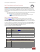
Digital Ally, Inc. | Model-Specific Wiring Diagrams
4-5
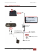
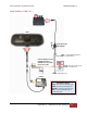
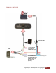
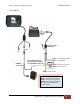
DVM-250Plus or DVM250 (with interface box)
RED = +12VDC Battery
BLUE = +12VDC Ignition
BLACK = Chassis Ground
VuLink Base Cable
008-01456-00
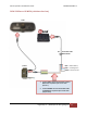
DVM
I/O Box
1. Connect WHITE wire from VuLink Base Cable to
WHITE wire of I/O box input sensor cable
(Sensor 5)
2. Connect BROWN wire from VuLink Base Cable
to BROWN wire of I/O box input sensor cable
(output alarm)
NC