860-00198-00_WIP Rev A March 2014 Operation and Installation Guide Wireless Link for and DVM systems Copyright © 2014, Digital Ally, Inc. All Rights Reserved. This publication may not be reproduced, stored in a retrieval system, or transmitted in whole or part in any form or by any means electronic, mechanical, recording, photocopying, or in any other manner without the prior written approval of Digital Ally, Inc.
VuLink Operation & Installation Guide 860-00198-00 REV A Table of Contents SECTION - 1: BEFORE YOU BEGIN............................................................................................................................ 1-1 OVERVIEW OF FEATURES ........................................................................................................................................................................ 1-1 INSTALLATION TOOLS NEEDED .......................................................
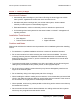
VuLink Operation & Installation Guide 860-00198-00 REV A Section - 1: Before you Begin Overview of Features Automatically start recordings on your Firstvu HD using the same triggers as vehicle video systems, regardless of whether the unit is mounted or worn Simultaneously start recordings with your vehicle video system, whether started manually on either system or automatically triggered Eliminate distraction, need to continuously record or remember to press record Link recordings from both syste
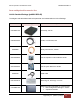
VuLink Operation & Installation Guide 860-00198-00 REV A Parts and Optional Accessories List VuLink Standard Package (pn#001-0950-00) The diagram and table below outline the parts that are included with the VuLink Package.
VuLink Operation & Installation Guide 860-00198-00 REV A Section - 2: VuLink Configuration Using VuVault to Configure your VuLink and FirstVuHD Prior to installation, VuLink must be configured either through the Mini Configuration Manager Software installer supplied on the VuLink internal memory or by using Digital Ally’s optional VuVault™ back-office software. If you have purchased VuVault™, follow the instructions on this page to configure and activate your VuLink.
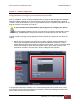
VuLink Operation & Installation Guide 860-00198-00 REV A Configuring VuLink VuLink acts as an 802.11n wireless access point which your FirstVu HD’s will use to communicate with your in-car video system. After you have made your selections, press Save. Network SSID The SSID is the wireless network name. This parameter specifies the VuLink SSID that your FirstVu HD’s are authorized to connect to. Password This parameter specifies the password or security phrase required to connect to VuLink.
VuLink Operation & Installation Guide 860-00198-00 REV A Encryption Type This parameter specifies the wireless encryption protocol required by VuLink. If selecting WPA2PSK as the authentication mode, choose AES as the encryption type. If selecting WPAPSK as the authentication mode, choose TKIP as the encryption type. Settings: TKIP, AES [default] Broadcast SSID Choose whether or not to broadcast the SSID. Broadcasting allows computers with wireless cards to find the network by browsing.
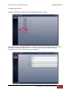
VuLink Operation & Installation Guide 860-00198-00 REV A Activating VuLink & FirstVu HD within VuVault After you have saved your desired configuration, proceed to Admin>Media Card Admin to activate each device. FirstVu HD Activation 1. Turn on your FirstVu HD & plug it into your computer using the supplied USB cable. 2. Select FirstVu HD as the device type. Click Refresh and the FirstVu HD will be displayed as a removable drive. 3. Highlight the drive with your mouse. 4.
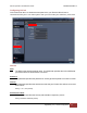
VuLink Operation & Installation Guide 860-00198-00 REV A Configuring VuLink Press the Add button to display the list of available options for VuLink. Select the Vulink tab. VuLink functions as an 802.11n wireless access point which your FirstVu HD’s will use to communicate with your in-car video system. After you have made your selections, return to the File tab to save your settings. Digital Ally, Inc.
VuLink Operation & Installation Guide 860-00198-00 REV A Settings Serial Number This is the serial number printed on your VuLink device. Type in your serial number here. (Example 09500061). SSID The SSID is the wireless network name. This parameter specifies the VuLink SSID that your FirstVu HD’s are authorized to connect to. Password This parameter specifies the password or security phrase required to connect to VuLink.
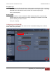
VuLink Operation & Installation Guide 860-00198-00 REV A 3. All Done! VuLink is now ready to be installed in your vehicle. Proceed to Section 3. Configuring your FirstVu HD Go to the FirstVu HD tab and check the “Use VuLink WAP settings” box as shown below. When done, return to the File tab to save your settings. Saving your FirstVu HD Settings 1. Plug in your FirstVu into the computer using the supplied USB cable. 2. From the File Tab, Select Save.
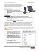
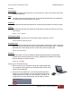
VuLink Operation & Installation Guide 860-00198-00 REV A DVM-800, DVM-250, and DVM-250Plus Device Configuration From your VuVault or Configuration Manager Settings tab, enable the desired sensor to be used with VuLink. Using this configuration, the FirstVu HD will be enabled to trigger device recordings and have a customized trigger name. This customized name will become a searchable parameter if using VuVault. 1. Go to the IF Box Input Sensors tab. Select the Sensor 5 row and press Edit. 2.
VuLink Operation & Installation Guide 860-00198-00 REV A Section - 3: Installation Instructions Step 1: Remove Body Trim 1. Remove front passenger side threshold 2. Pull the door seal away and remove any side trim pieces 3. Remove the passenger side front interior A-pillar cover 4. remove the passenger side kick panel & pull back the carpet to expose the vehicle chassis Digital Ally, Inc.
VuLink Operation & Installation Guide 860-00198-00 REV A Step 2: Power Ignition, and Ground Connections Remove 6 to 7 inches of the outer jacket at the bare end of the power cable. The Red wire of the DVM power cable should be connected to the vehicle constant +12Vdc. Connect the Blue wire to the ignition switch where +12vdc is only present when the vehicle ignition key is in the ON position. The Black wire of this power cable connects directly to the vehicle’s chassis.
VuLink Operation & Installation Guide 860-00198-00 REV A Step 4: VuLink Installation Plug the base cable into the connector on the side of VuLink. Prep the windshield glass with alcohol to remove any dirt or debris. Using the included double-sided tape, attach VuLink to an unobstructed location on the windshield below the roofline. To avoid possible interference from other vehicle equipment, do not mount VuLink near other vehicle antennas.
VuLink Operation & Installation Guide 860-00198-00 REV A Section - 4: Model-Specific Wiring Diagrams DVM-100 / DVM-400 VuLink Relay Wiring WHITE = connect to Emergency lights WHITE = connect to chassis ground YELLOW = connect to chassis ground RED = connect to BROWN wire on VuLink base cable DVM NC VuLink Base Cable 008-01456-00 Connect WHITE wire from VuLink Base Cable to WHITE wire of DWM800 sensor cable DWM800 Sensor Cable RED = +12VDC Battery BLUE = +12VDC Ignition Relay (see belo w) WHITE =
VuLink Operation & Installation Guide 860-00198-00 REV A DVM-500Plus / DVM-750 DVM DVM NC VuLink Base Cable 008-01456-00 BLUE = +12VDC Switched Ignition RED = +12VDC Battery Connect WHITE wire from VuLink Base Cable to ORANGE wire of I/O BOX input sensor cable Relay (see belo w) WHITE = Emergency Light Input WHITE = Tie to ground BLACK = Chassis Ground I/O Box VuLink Relay Wiring WHITE = connect to Emergency lights WHITE = connect to chassis ground YELLOW = connect to chassis ground RED = connect
VuLink Operation & Installation Guide 860-00198-00 REV A DVM-800 / DVM-LiVE DVM NC I/O Box Connect BROWN wire from VuLink Base Cable to BROWN wire of I/O box sensor cable VuLink Base Cable 008-01456-00 RED = +12VDC Battery BLACK = Chassis Ground Connect WHITE wire from VuLink Base Cable to WHITE wire of I/O box sensor cable (Sensor 5) BLUE = +12VDC Switched Ignition Digital Ally, Inc.
VuLink Operation & Installation Guide 860-00198-00 REV A DV-440Ultra NC VuLink Base Cable 008-01456-00 9 pin DWM800 Sensor Cable Connect WHITE wire from VuLink Base Cable to WHITE wire of DWM800 sensor cable BLUE = +12VDC Switched Ignition RED = +12VDC Battery Relay WHITE = Emergency Light Input WHITE = Tie to Ground BLACK = Chassis Ground VuLink Relay Wiring WHITE = connect to Emergency lights WHITE = connect to chassis ground YELLOW = connect to chassis ground RED = connect to BROWN wire on VuL
VuLink Operation & Installation Guide 860-00198-00 REV A DVM-250Plus or DVM250 (with interface box) DVM NC I/O Box VuLink Base Cable 008-01456-00 RED = +12VDC Battery BLUE = +12VDC Ignition BLACK = Chassis Ground 1. Connect WHITE wire from VuLink Base Cable to WHITE wire of I/O box input sensor cable (Sensor 5) 2. Connect BROWN wire from VuLink Base Cable to BROWN wire of I/O box input sensor cable (output alarm) Digital Ally, Inc.
VuLink Operation & Installation Guide 860-00198-00 REV A Generic Input Source NC VuLink Base Cable 008-01456-00 RED = +12VDC Battery BLUE = +12VDC Ignition Relay VuLink Relay Wiring WHITE = +12VDC Auxiliary output (enabled when VuLink is activated) WHITE = connect to Input Trigger WHITE = connect to chassis ground YELLOW = connect to chassis ground RED = connect to BROWN wire on VuLink base cable WHITE = +12VDC Generic Input Trigger WHITE = Tie to Ground BLACK = Chassis Ground Digital Ally, Inc.
VuLink Operation & Installation Guide 860-00198-00 REV A Section - 5: Operation Power Control Power to VuLink is controlled through your vehicle’s ignition. There are no manual controls for powering the unit on and off. When ignition is cycled, the VuLink boot-up process will begin. The red and green status indicators will flash in unison until boot up is complete. When ignition is turned off, the VuLink will enter low power standby and will then power off.
VuLink Operation & Installation Guide 860-00198-00 REV A VuLink™ LED Status Indicators Battery Power present to VuLink Power-on Sequence Searching for Wireless Link GREEN YELLOW RED ON -- -- ON Flash in unison -- Flash -- Wireless Link Established -- ON -- Record in Progress -- -- ON Covert Mode OFF OFF OFF Ignition Off ON OFF OFF Firmware Upgrade ON Alternating flash FirstVuHD™ LED Status Indicators The FirstVuHD yellow status LED will be on whenever a wireless link is est
VuLink Operation & Installation Guide 860-00198-00 REV A Section - 6: Support Software Updates Log on to www.digitalallyinc.com/tech-support.php and Register for an Account to be an Authorized User. By registering you will be able to download all the latest software updates and be notified of future updates. Performing a Reset Using a small device such as a paper clip or eye-glass screwdriver, press the recessed reset button that is located as shown to the right.
VuLink Operation & Installation Guide 860-00198-00 REV A Section - 7: Warranty Information We warranty that our wireless link, Model VuLink™, will be free from defects in workmanship and material for a period of 12 months from the date of purchase by the original purchaser. If any defect is discovered through normal and proper use of the unit during this period, the defect will be repaired or the unit will be replaced at our factory or at one of our authorized service centers at no cost to the purchaser.
VuLink Operation & Installation Guide 860-00198-00 REV A Section - 8: Contact Information 9705 Loiret Blvd Lenexa, KS 66219 Website: www.digitalallyinc.com Support E-Mail: support@digitalallyinc.com Sales E-Mail: sales@digitalallyinc.com Phone: 913-814-7774 Fax: 913-814-7775 Sales / Support Toll Free: 1-800-440-4947 * Specifications subject to change without notice. Digital Ally, Inc.
VuLink Operation & Installation Guide 860-00198-00 REV A Section - 9: Regulatory This device complies with Part 15 of the FCC Rules. Operation is subject to the following two conditions: (1) This device may not cause harmful interference, and (2) This device must accept any interference received, including interference that may cause undesired operation. This equipment has been tested and found to comply with the limits for a Class B digital device, pursuant to part 15 of the FCC Rules.