
Specifications


DigiPoS Retail Blade
™
Manual
Powered Port Over Current Protection
All of the voltages on the I/O ports are protected by a poly recoverable fuse rather than a
conventional fuse. This means if a particular voltage draws too much current, the poly
recoverable fuse will break the circuit causing a disruption of the voltage. To re-set the
fuse, power the system down completely (including operating the switch on the external
power supply) and leave the system powered off for at least 30 seconds. When the power
is re-applied, the fuse should have returned to normal. If a fuse open circuits, it is either an
indication of a problem with a powered peripheral or that voltage is drawing too much
current. If you have to repeat the above procedure, more than once in any 24-hour period,
please contact DigiPoS Systems or your DigiPoS Systems representative for advice.
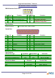
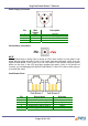
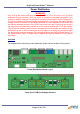
Power Board Configuration
Jumper Port Setting Default Setting
J1 COM1
0 (Standard RS232), 5, 12,
24
0 (Standard RS232)
J2 COM2
0 (Standard RS232), 5, 12,
24
0 (Standard RS232)
J3 COM3
0 (Standard RS232), 5, 12,
24
0 (Standard RS232)
J4 COM4
0 (Standard RS232), 5, 12,
24
0 (Standard RS232)
J5 Cash Drawer 12V, 24V 24V
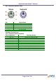
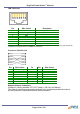
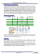
A typical configuration sticker giving details on what voltage has been set with regard to
which port. This sticker can usually be found on the inside of the front flap. Please note
the Modem position (standard RS232) if required.
Applications
Unless specified at time of order, the Retail Blade™ will be shipped with the default
jumper settings of 0 Volts. If you wish to have a particular set-up, then please contact
DigiPoS Systems or your DigiPoS Systems representative.
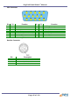
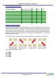
The 0V option will permit the connection of an external modem to the DigiPoS and allows
the use of the ring indicator (RI) signal. The Ring Indicator is the signal the modem gives
to the Retail Blade™ to tell the software that another device is trying to connect to it. The
RI signal is normally found on pin 9 of the d-type connectors.
Page 48 of 103