
Specifications
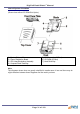


DigiPoS Retail Blade
™
Manual
Removing the CPU Heat Dissipation Assembly and the CPU Cont.
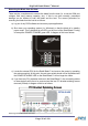
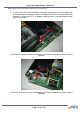
g) Once you can see the CPU, it is removed by operating the locking bar on the side
of the CPU socket. This bar operates in the same fashion as the heat dissipation
assembly clamps. The diagrams below show a close up of the CPU socket and the
locking bar.
Push down on the lever, move it horizontally away from the CPU socket and then
rotate it vertically.
h) The CPU can now be removed.
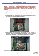
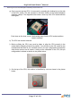
i) Before re-fitting the CPU, care must be taken to align the CPU correctly in the
socket before clamping it back into position. You will see on the 478 socket on the
motherboard that there is one rounded corner in the pin configuration whereas the
other three corners are all square. Looking at the underside of the CPU, this pin
configuration is evident as shown in the picture below:
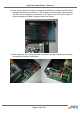
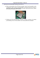
j) On the top of the CPU, this section is identified by a dot as shown in the picture
below:
Page 37 of 103