PH-6000B System Designed for Retail PoS Big impact. Small space. DigiP oS 5V 2 3 1 User Guide Release Version 1.
DigiPoS PH-6000B Table of Contents Preface .............................................................. 2 FCC Radio Frequency Interference Statement ................................ 2 Copyright Statement .............................................................. 2 Notice ............................................................................... 2 Safety Instructions ................................................................ 3 Overview ......................................................
Preface Preface FCC Radio Frequency Interference Statement This equipment has been tested and found to comply with the limits for a class A digital device. These limits are designed to provide reasonable protection against harmful interference when the equipment is operated in a commercial environment. This equipment generates, uses and can radiate radio frequency energy and, if not installed and used in accordance with the instruction manual, may cause harmful interference to radio communications.
DigiPoS PH-6000B Safety Instructions • Always read the safety instructions carefully. • Keep this Manual for future reference. • Keep this equipment away from humidity and dust. • Lay the equipment on a reliable flat surface before setting it up. • The openings on the enclosure are for air convection, hence protecting the equipment from overheating. DO NOT COVER THESE OPENINGS. For a more detailed explanation about ventilation requirements, please check the appropriate section within this document.
Overview Overview Congratulations on your purchase of the DigiPoS PH-6000B. You are now the owner of a state-of-the-art POS system. The DigiPoS PH-6000B offers unparalleled features, speed and performance combined with exceptional reliability. It is unrivalled by other conventional VIA/Intel based PCs within the EPoS industry. Package List When you receive the DigiPoS PH-6000B, ensure all the following items are present in the package.
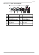
DigiPoS PH-6000B Front Side Components 10 DigiPoS 2 5V 3 1 No. 1 2 Name 3 4 5 6 7 8 9 No. Name 1 5V PoweredUSB port 6 CD-ROM 2 3-position keylock 7 HDD status LED 3 CD-ROM LED 8 Reset button 4 CD-ROM tray eject button 9 Power button 5 Emergency eject hole 10 Power LED Rear Side Components VIA System (PH-6000B-300) 24V DC INPUT 24V 12V + 1 2 3 No. 5 4 Name 5 6 No.
Overview Intel System (PH-6000B-700/ PH-6000B-800) 24V DC INPUT 24V 12V + 1 2 No. 3 4 Name 5 No.
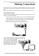
DigiPoS PH-6000B Making Connections By using the ports on the rear side of your DigiPoS PH-6000B, you can connect it to various devices. Refer to the procedures described in this section to make connections to these ports. Note: The PH-6000B-300 is used to illustrate the connections throughout this section. Connecting the Power Before powering on the DigiPoS PH-6000B, you need to follow the steps below to connect the power cord and power adapter. 1.
Making Connections Connecting USB Powered Devices The DigiPoS PH-6000B provides a wide range of output voltages from its PoweredUSB ports: 5V, 12V, and 24V. These ports allow the connected devices to be powered directly from your DigiPoS PH-6000B. You can also use these ports for standard USB data transmission. Note: To find out the required voltage of the USB peripheral device to be connected, please refer to the device’s manual or contact your peripheral device dealer.
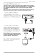
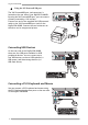
DigiPoS PH-6000B Using the 24V PoweredUSB port The 24V PoweredUSB port (red connector) is located on the rear side of your DigiPoS PH-6000B. By using the 24V PoweredUSB port, you can connect printers powered by a 24V current. 24V DC INPUT 24V 12V + Connect one end of the supplied 24V USB powered cable to the 24V PoweredUSB port (red) on the DigiPoS PH-6000B. Connect the two connectors at the other end to a supported printer.
Making Connections Connecting to a Network You can set up a ethernet network connection via the provided RJ45 LAN port. Plug one end of the LAN cable into the RJ45 LAN port on the rear side of the DigiPoS PH-6000B and the other end into an available wall outlet or hub as shown. 24V DC INPUT 24V 12V + 012520 Connecting Speakers The line-out port on the rear side of the DigiPoS PH6000B allows you to connect external speakers or headphones.
DigiPoS PH-6000B 11
DigiPoS PH-6000B Using Your DigiPoS PH-6000B Powering on the DigiPoS PH-6000B To start using your DigiPoS PH-6000B, you must set up the power connections, and examine to ensure that each piece of equipment is securely connected to its port. Then press the power button to power on the system as shown. For detailed information on each connection, see “Making Connections” on page 7. DigiPoS 2 5V 3 1 Power LED The blue power LED lights when your DigiPoS PH-6000B is turned on.
Using Your DigiPoS PH-6000B 3-Position Keylock Operation 2 The DigiPoS PH-6000B has a keylock located on the front panel. This 3position keylock provides an additional layer of security to your DigiPoS PH-6000B. Use the provided keys to control access to the power button, reset button, and CD-ROM. Refer to the table below for information on which components are accessible in each key position.
DigiPoS PH-6000B Specification DigiPoS PH-6000B VIA System CPU Memory HDD Optional parts Operating temperature Power supply Dimensions 13 DigiPoS PH-6000B Intel System VIA C7 1GHz Intel Celeron M 600MHz / 1GHz Supports one DDRII 256MB/ 512MB/1G DIMM, may vary according to the model Supports one DDR 256MB/512MB/ 1G DIMM, may vary according to the model Supports one 2.5” Supports one 2.