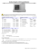
Modules Programming Guide Programming Methods The modules can be programmed using the following methods: 1) Through the WinLoad Security Management Software. The modules can be programmed at 19,200 baud (or 38,400 baud with DGP-NE96) by connecting locally using a 306 adapter, remotely through a modem or locally using an ADP-1 adapter at 300 baud. Refer to the WinLoad Help for more information. 2) The module can also be programmed by using the Module Broadcast Feature of the control panel.
Table of Contents Grafica Graphic LCD Keypad Module................................................................................................. 3 LCD Keypad Module............................................................................................................................. 5 48-Zone LED Keypad Module .............................................................................................................. 9 Annunciator Module ..........................................................
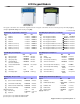
Grafica Graphic LCD Keypad Module DNE-K07 V1.3 Grafica Keypads can be used with DGP-848 and DGP-NE96 control panels only. Grafica will not function with DGP-48 control panels. The keypad’s serial number can be found on the keypad’s PC board. The keypad’s serial number can also be viewed by pressing and holding the [0] key, entering the [INSTALLER CODE] and then entering section [000].
Copy Contents of the Grafica Keypad to the Memory Key: 1) Insert the Memory Key onto the keypad’s connector (refer to Memory Key Connector on page 4). Ensure that the write protect jumper is on (refer to Memory Key (PMC-3) below). 2) To copy the contents to the Memory Key, enter the keypad’s programming mode and enter section [110]. 3) Once the keypad emits a confirmation beep, wait for a second confirmation beep and then remove the Memory Key.
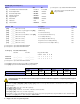
LCD Keypad Module DGP2-641 V1.1 DGP2-641R V2.0 DGP2-641BL V1.1 DGP2-641RB V2.0 The keypad’s serial number can be found on the keypad’s PC board. The keypad’s serial number can also be viewed by pressing and holding the [0] key, entering the [INSTALLER CODE] and then entering section [000].
SECTION [006]: General Options 3 † Option OFF ON [1] Card Activates Door Unlocked Schedule N Disabled. [2] Door Left Open Alarm U Disabled [3] Door Forced Open Alarm U Disabled [4] PIN Entry on Keypad U Enabled * [5] Keypad Tamper U Disabled [6] Relock Door U Disabled [7] Future Use N N/A [8] Unlock on REX U Disabled Section † Section/option is only available with DGP2-641R/RB. U 1 second N Enabled * This option cannot be turned ON and will always remain OFF.
Table 1: Message Programming Special Function Keys Key [STAY] [FORCE] [ARM] Function Details Insert Space Press the [STAY] key to insert a blank space at the current cursor’s position. Delete Press the [FORCE] key to delete the character or blank space found at the current cursor’s position. Delete Until the End Press the [ARM] key to delete all characters and spaces to the right of the cursor and at the cursor’s position.
Using the Memory Key [510] Download all from the Memory Key (LCD keypad sections [001] to [396] and all labels and messages) to the LCD keypad. [520] Copy the LCD keypad sections [001] to [396] and all labels and messages to the Memory Key. Download Contents of the Memory Key to the LCD Keypad 1) Insert the Memory Key onto the keypad’s connector labelled “KEY”. 2) To download the contents of the Memory Key, enter the keypad’s programming mode and enter section [510].
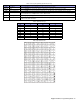
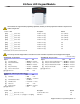
48-Zone LED Keypad Module DGP2-648 V1.0 This model does not support installer programming capabilities, therefore you cannot program other modules or the panel on the combus using this unit.
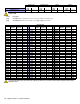
Event Group Feature Group Section Start # Section End # Section Section PGM Activation [014] __/__/__ [015] __/__/__ [016] __/__/__ [017] __/__/__ PGM Deactivation [018] __/__/__ [019] __/__/__ [020] __/__/__ [021] __/__/__ Refer to Appendix 1: Programming PGMs on page 41 for the PGM Table. Only Event Groups 000 to 055 can be used to program the module’s PGM. Section Description [030] Test PGM: Activates the PGM for 8 seconds to verify if the PGM is functioning properly.
Annunciator Module DGP2-ANC1 V1.0 Program the DGP2-ANC1 using the Winload Software or the control panel’s Module Broadcast feature. Refer to the Digiplex (DGP-848 or DGP-NE96) Reference & Installation Manual for more details. The DGP2-ANC1’s serial number is located on the module’s PC board.
Outdoor High-Security Digital Motion Detector Modules DG85 V1.1 Operational Mode Digigard DG85 can function in two operational modes (see Table 4 below): DGP2 Mode or Relay Mode. When set to Relay Mode, DG85 functions like any standard motion detector by communicating its alarm and tamper signals via relays. When set to DGP2 Mode, DG85 functions like a DGP2 motion detector module by communicating alarm signals, tamper signals, data and detector settings via the combus.
Motion Detector Modules DGP2-50 V2.0 DGP2-60 V2.0 DGP2-70 V2.0 U = Default setting SECTION [001] : General Options Option OFF [1] Single/Dual Edge Processing [2] Alarm Indication (red LED illuminates for 5 secs.
Magellan Wireless Expansion Module MG-RCV3 V2.0 The Module Broadcast feature of the Digiplex (DGP-848 and DGP-NE96) control panels is not supported by the Magellan Wireless Expansion Module.
Remote Control Programming Remote Control Assignment to the Receiver Remote Control Assignment to a User Access Code Remote Control Button Programming (refer to Tables 5 and 6 below) Section & User Name Section User # Section [201] :____________________________________ [301] __/__/__ [401] ( __/__ ) ( __/__ ) ( __/__ ) ( __/__ ) [202] :____________________________________ [302] __/__/__ [402] ( __/__ ) ( __/__ ) ( __/__ ) ( __/__ ) [203] :____________________________________ [303] _
4-PGM Expansion Module APR3-PGM4 V2.
1-PGM Expansion Module APR3-PGM1 V2.
8-zone Expansion Module APR3-ZX8 V2.0 U = Default setting SECTION [001] : General Options Option OFF ON U Disabled N Enabled [1] Tamper Recognition [2] PGM Deactivation After U Deactiva- N PGM Timer [3] PGM normal state U N.O. N N.C.
4-zone Expansion Module APR3-ZX4 V1.
1-zone Expansion Module DGP2-ZX1 V2.0 U = Default setting SECTION [001] : General Options Option [1] Tamper Recognition [2] to [8] Future Use OFF ON N N/A N N/A U Disabled N Enabled INPUT SPEED = BASE TIME x TIME VALUE (Default: 600mS) Base Time (000 to 002)* SECTION Data [002] ___/___/___ *For the Base Time, using Level Programming (refer to page 1), press the [ENTER]. Base Time Multipliers: 000 = 15 ms, 001 = 1 second, 002 = 1 minute.
Printer Module APR3-PRT1 V2.
SECTION [007] : Automatic Printing of Zone Status (41 to 48) Option OFF [1] Print Status of Zone 41 [2] Print Status of Zone 42 [3] Print Status of Zone 43 [4] Print Status of Zone 44 [5] Print Status of Zone 45 [6] Print Status of Zone 46 [7] Print Status of Zone 47 [8] Print Status of Zone 48 ON U Disabled N Enabled U Disabled N Enabled U Disabled N Enabled U Disabled N Enabled U Disabled N Enabled U Disabled N Enabled U Disabled N Enabled U Disabled N Enabled SECTION [009] : Automatic
U = Default setting SECTION [015] : Printer Setup Options Option [1] SECTION [016] : Serial Port Setup Options OFF Parallel Port [2] Future Use [3] Off-line Status Ignored [4] Paper Empty Status Ignored [5] Printer Fault Status Ignored [6] Printer Busy Status Ignored [7] Future Use [8] Future Use ON Option U Disabled N Enabled N N/A [1] N N/A OFF N See Table N See Table N See Table N See Table [2] & [3] U Disabled N Enabled ON U Disabled N Enabled Serial Port U Disabled N Enable
[041] __/__/__ (000 to 255)** Tamper/Tamper Restore Events (Event Start # Selection) 000 [042] __/__/__ (000 to 255)** Tamper/Tamper Restore Events (Event End # Selection) 000 [043] __/__/__ (000 to 255)** Trouble/Trouble Restore Events (Event Group Selection) 000 [044] __/__/__ (000 to 255)** Trouble/Trouble Restore Events (Feature Group Selection) 000 [045] __/__/__ (000 to 255)** Trouble/Trouble Restore Events (Event Start # Selection) 000 [046] __/__/__ (000 to 255)** Trouble/Troub
InTouch Voice-Assisted Arm/Disarm Module APR3-ADM2 V2.
Access Control Module DGP2-ACM1P V2.0 U = Default setting * = V2.0 or higher ** = V1.1 or higher *** = V1.
[009] __/__/__ (001 to 255 seconds) Time to start pre-alarm before alarm is triggered Door Left Open Pre-Alarm Timer 015 [010] __/__/__ (001 to 255 seconds) Beep timer for Door Left Open Alarm 005 [011] __/__/__ (001 to 255 seconds) Beep timer for Door Forced Open alarm 005 [012] __/__/__ (000 to 255; refer to option [3] in section [004]) PGM timer 005 Section [013]: Door Unlocked Schedule Start Time End Time Days (turn ON or OFF) S M T W T F S H Schedule A: ___ ___ : ___ ___ ___ ___ :
Section Description [070] Delete All Safe Mode Access Cards* [071] Delete Safe Mode Access Card 1* [072] Delete Safe Mode Access Card 2* [073] Delete Safe Mode Access Card 3* [074] Delete Safe Mode Access Card 4* Enter the desired section to delete the corresponding access card(s).
Power Supply Module DGP2-PS17 V1.0 U = Default setting SECTION [001] : General Options Option OFF ON [1] Tamper Recognition U Disabled N Enabled [2] Battery Charge Current U 350mA N 850mA [3] PGM Deactivation After U Deactiva- N PGM Timer [4] PGM Base Time U 1 second N 1 minute A 40VA transformer is required when selecting the 850mA battery charge current. Using a 20VA transformer with a battery charge current of 850mA may damage the system.
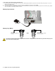
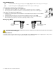
Module Connection Drawings Module Connection Overview Figure 1: Connecting the Combus Figure 3: Connecting a 50mA PGM Output Some modules’ PGM output is comprised of one 50mA output. Connect the PGM output as shown below. Module Module Digiplex control panel (DGP-848/DGP-NE96) Combus Figure 2: Connecting a 5A PGM Output Module LED Indications Some modules’ PGM output(s) are comprised of one or more 5A relays. Connect the PGM output as shown below.
Grafica Graphic LCD Keypad Module (DNE-K07) Mounting the Metal Wall Plate 1) Place the wall plate to desired position. 2) Drill and insert screws into holes labelled “A”. Please Note: The Grafica keypad is best viewed at an angle between 20° and -10°. Please Note: Grafica’s keypad cover requires a minimum clearance of 9cm (3.5in). Mounting Grafica to the Wall Plate 1) Place Grafica’s back plate flush against the mounted metal wall plate.
LCD Keypad Module (DGP2-641/BL/R/RB) 48-Zone LED Keypad Module (DGP2-648) LCD Keypad (DGP2-641/BL/R/RB) LED Keypad (DGP2-648) Memory Key Connector Combus Combus To Digiplex control panel (DGP-848 or DGP-NE96) To Digiplex control panel (DGP-848 or DGP-NE96) Please Note: The keypad’s anti-tamper switch will communicate its status to the control panel via the combus. Door Contact * The keypad’s zone follows the control panel’s EOL definition. The zone speed is set at 600mS and cannot be programmed.
Annunciator Module (DGP2-ANC1) Use a knife to cut away two holes approximately 75mm from the Annuciator’s back plate. Cut a square in front of the guide clip (A) and at the top of the rim (B). Dotted lines indicate cutting lines. Remove B from any Annunciator that will have additional modules stacked on top of it as shown in Figure 3 (below). Uppermost Annunciators such as module 3 in Figure 3 or stand-alone modules do not require the removal of B. Remove the plastic square from keypad’s top back plate E.
Motion Detector Modules (DGP2-50/60/70) Addressable Digital Motion Detectors (DGP2-50/60) Addressable High-Security Motion Detectors (DGP2-70) PCB Height Adjustment DGP2-50/60/70 is designed for optimal performance at a height of 2.1m (7ft), but can be installed lower or higher. After you have installed the motion detector, ensure that the PCB Height Markings match the installation height. The installation height is measured from the ground to the base of the motion detector's cover.
Magellan Wireless Expansion Module (MG-RCV3) Anti-Tamper Switch The anti-tamper switch can also be used to disable a "Locate" request coming from the control panel. “PROGRAM” Button: Not used For information on the Magellan Wireless Receiver Module’s LEDs, refer to Module LED Indications on page 30. Refer to Module Connection Overview on page 30 for information on how to connect the Magellan Wireless Receiver Module to the combus (Figure 1) and its PGM outputs (Figure 2).
4-zone Expansion Module (APR3-ZX4) For information on the 4-zone Hardwire Module’s LEDs, refer to Module LED Indications on page 30. A "Locate" request coming from the control panel can be disabled by pressing the "Disable Locate" switch. Refer to Module Connection Overview on page 30 for information on how to connect the 4-zone Hardwire Module to the combus (Figure 1). Before commencing with the connections, please read the General Warnings listed on page 30. External AntiTamper Switch (N.C.
Printer Module (APR3-PRT1) For information on the Printer Module’s LEDs, refer to Module LED Indications on page 30. Refer to Module Connection Overview on page 30 for information on how to connect the Printer Module to the combus (Figure 1) and its PGM output (Figure 3). Before commencing with the connections, please read the General Warnings listed on page 30.
Access Control Module (DGP2-ACM1P) For information on the Access Control Module’s LEDs, refer to Module LED Indications on page 30. Refer to Module Connection Overview on page 30 for information on how to connect the Access Control Module’s PGM output (Figure 3). Before commencing with the connections, please read the General Warnings listed on page 30. Caution: Disconnect battery before replacing fuse.
Power Supply Module (DGP2-PS17) For information on the Power Supply Module’s LEDs, refer to Module LED Indications on page 30. Caution: Disconnect battery before replacing the fuse. Control Panel (DGP-848/DGP-NE96) Improper connection of the transformer may result in damage to the system. The 12Vdc power supply output will automatically shut down if the current exceeds 1.1A. A 40VA transformer is required when selecting the 850mA battery charge current.
Hub and Bus Isolator Module (APR3-HUB2) From other modules or a Spectra or Digiplex control panel To other combus modules To other combus modules Power supply with dedicated transformer Power supply with dedicated transformer To other combus modules To other combus modules Power supply with dedicated transformer Power supply with dedicated transformer The APR3-HUB2 is non-addressable, therefore you can connect an unlimited amount of hubs to the combus without affecting the total number of modules s
Appendix 1: Programming PGMS A PGM is a programmable output that toggles to its opposite state (i.e. a normally open PGM will close) when a specific event occurs in the system. For example, a PGM can be used to reset smoke detectors, activate strobe lights, open/close garage doors and much more. When a PGM closes, the module supplies a ground to the PGM (transistor PGM), or the link between N.C. and COM is established (Relay PGM), which activates any device or relay connected to it.
Event Group 004 (cont’d) 005 006 007 008 009 010 011 Event Non-reportable Event User Code entered on Keypad User/Card Access on door Bypass Programming Access TX Delay Zone Alarm Arming with Master Arming with User Code Arming with Keyswitch Feature Group 000 013 014 Disarm with User Code 42 - Digiplex Modules Programming Guide End # 010 010 NEware User Logout 011 011 User Initiated Callup 012 012 Force Answer 013 013 Force Hangup 014 014 Any non-reportable event Not
Event Group 015 016 017 018 019 020 021 022 Event Disarm with Keyswitch Disarm after alarm with Master Disarm after alarm with User Code Disarm after alarm with Keyswitch Alarm Cancelled with Master Alarm Cancelled with User Code Alarm Cancelled with Keyswitch Special Disarm Events Feature Group Feature Start # End # 000 Keyswitch numbers 001 to 032 001 to 032 255 Any keyswitch Not Used Not Used 000 User Codes 001 to 255 001 to 255 001 to 255 001 User Codes 256 to 511 000 t
Event Group 030 031 Event Special Alarm Duress Alarm by User 032 Zone Shutdown 033 Zone Tamper 034 Zone Tamper Restore 035 Special Tamper 036 Trouble Event Feature Group 000 Trouble Restore Module Trouble Module Trouble Restore 001 001 Fire Panic (Keys 7 & 9) 002 002 Recent Closing 003 003 Police Code 004 004 Global Shutdown 005 005 Not Used Not Used User Codes 001 to 255 001 to 255 001 to 255 001 User Codes 256 to 511 001 to 255 001 to 255 002 User Codes 512 to
Event Group Event Feature Group Feature Start # End # 040 Fail to Communicate on telephone Number 000 Telephone Number 001 to 004 001 to 004 255 Any telephone number Not Used Not Used 041 Low Battery on Zone 001 to 096 001 to 096 042 Zone Supervision Trouble 001 to 096 001 to 096 043 Low Battery on Zone Restored 001 to 096 001 to 096 044 Zone Supervision Trouble Restored 001 to 096 001 to 096 045 046 047 Special Events Early to Arm by User Late to Arm by User 000 255 =
Event Group 064 065 066 Event Status 1 Status 2 Status 3 067 Future Use 070 Clock Feature Group See Note 1 on page 46 See Note 1 on page 46 See Note 1 on page 46 Future Use Feature Start # Armed 000 End # 000 Force Armed 001 001 Stay Armed 002 002 Instant Armed 003 003 Strobe Alarm 004 004 Silent Alarm 005 005 Audible Alarm 006 006 Fire Alarm 007 007 Ready 000 000 Exit Delay 001 001 002 Entry Delay 002 System in Trouble 003 003 Alarm in Memory 004 004
Actions Utility Key Event Keypad Utility Keys Keyswitch Inputs (definition = [3]) Keyswitch Inputs (definition = [4]) Remote Control Utility Key Event 13 N/A Utility Key Event 14 N/A KS** Input 13 opens KS** Input 7 opens N/A KS** Input 14 opens KS** Input 7 closes Utility Key Event 15 N/A N/A KS** Input 15 opens KS** Input 8 opens N/A Utility Key Event 16 N/A KS** Input 16 opens KS** Input 8 closes N/A Utility Key Event 17 N/A KS** Input 17 opens KS** Input 9 opens N/A Utility
780 Industriel Blvd., Saint-Eustache (Quebec) J7R 5V3 CANADA Tel.: (450)491-7444 Fax: (450) 491-2313 www.paradox.