
User manual


72.0 Megapixel H.264 Network IP Camera User Manual
SECTION 2: INSTALLATION AND SETUP
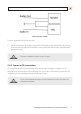
Audio in/out wiring schematic
To connect a speaker and/or microphone to the camera:
1. Strip 1/4” of insulation from the microphone and speaker wires and insert them into the terminal block in the pin locations
shown in the terminal block gure above. Note that the common (ground) leads of the microphone and speaker share the
same terminal block pin.
CAUTION
Do not attach a headphone or earphone directly to the camera.
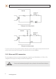
2.4.2 Sensor in (DI) connection
The camera provides one channel for sensor input that can be connected to either a voltage type or relay type sensor. For
voltage type sensors, the camera allows an input voltage range of 0 ~ 24 V DC, with a 1 V DC threshold (see Specications). The
conguration of the sensor input wiring is illustrated in the following schematics.
CAUTION
Do not exceed the maximum input voltage or the relay switching rate. Refer to the specications in this
manual for more information.