
User manual


92.0 Megapixel H.264 Network IP Camera User Manual
SECTION 2: INSTALLATION AND SETUP
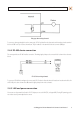
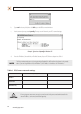
Relay type alarm wiring schematic
To connect an alarm reporting device to the camera, strip 1/4” of insulation from the alarm wires and insert them into the terminal
block in the DO 1 and C pin locations shown above. The pin marked C on the terminal block is the common (COM) pin.
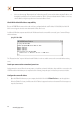
2.4.4 RS-485 device connection
The camera provides one RS-485 interface connection. The wiring signal polarity to the connector block is shown in the schematic
below.
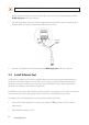
RS-485 device wiring schematic
To connect an RS-485 device wiring to the camera, strip 1/4” of insulation from the wires and insert them into the terminal block in
the RS-485 pin locations shown above. Observe the signal polarity shown in the schematic.
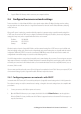
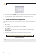
2.4.5 LAN and power connection
Your camera can be powered locally with a 12 V DC adapter, or across the LAN (PoE, see Appendix B). If using PoE powering, you do
not need to attach a power adapter to the camera.