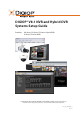
DIGIOP® V8.1 NVR and Hybrid DVR Systems Setup Guide Products: AH Series, EH Series, PH Series Hybrid DVRs AI Series, EI Series NVRs PLEASE READ THIS MANUAL BEFORE USING YOUR SYSTEM, and always follow the instructions for safety and proper use. Save this manual for future reference.
Revision History Revision Date Reason for Change 1.0 5/12/12 Initial release. CAUTION Operate this system only in environments where the temperature and humidity is within the recommended range. Operation in temperatures or at humidity levels outside the recommended range may cause electric shock and shorten the life of the product. Refer to the specifications for each system component for more information.
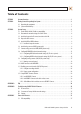
Table of Contents SECTION 1 SECTION 2 SECTION 3 APPENDIX A APPENDIX B APPENDIX C Systems Overview. . . . . . . . . . . . . . . . . . . . . . . . . . . . . . . . . . . . . . . . . . . . . . . . . . . . . . . . . . . . . . . . . . . . 1 Getting Started: Unpacking Your System . . . . . . . . . . . . . . . . . . . . . . . . . . . . . . . . . . . . . . . . . . . . . . . . 3 2.1 Unpacking the equipment. . . . . . . . . . . . . . . . . . . . . . . . . . . . . . . . . . . . . . . . . . . . . . . . . . . . . . .
APPENDIX D APPENDIX E iv C.2 Power classification . . . . . . . . . . . . . . . . . . . . . . . . . . . . . . . . . . . . . . . . . . . . . . . . . . . . . . . . . . . . . . . . . 37 Configure the DIGIOP® Black IP Camera Address . . . . . . . . . . . . . . . . . . . . . . . . . . . . . . . . . . . . . . . . . 38 D.1 Install IPAdmin Tool . . . . . . . . . . . . . . . . . . . . . . . . . . . . . . . . . . . . . . . . . . . . . . . . . . . . . . . . . . . . . . . . . 38 D.
SECTION 1: SYSTEM OVERVIEW SECTION 1 Systems Overview DIGIOP® Network Video Recorder (NVR) and Hybrid Digital Video Recorder (hDVR) servers with the DIGIOP ELEMENTS™ video and data management software feature state-of-the-art management for advanced analog and IP cameras with real-time data capture. DIGIOP ELEMENTS is a seamless suite of video and data intelligence products includes that combine raw video with information from back-office systems with video analytics.
SECTION 1: SYSTEM OVERVIEW server configuration settings at DIGIOP®. For hosted enterprise management, the NVR and hDVR servers must be accessible through the Internet. The selection of using either local or hosted enterprise management is made through the Enterprise Configuration Application in the Windows Start menu.
SECTION 2: GETTING STARTED: UNPACKING YOUR SYSTEM SECTION 2 Getting Started: Unpacking Your System For most installations, DIGIOP® NVR and hDVR systems come with everything needed to install and operate your system. 2.1 Unpacking the equipment Remove the equipment from its packaging and place it on a flat, clean surface. Inspect each item. If any visible damage is present, contact your supplier for a replacement. Verify that your order is complete.
SECTION 2: GETTING STARTED: UNPACKING YOUR SYSTEM • • Lighting – Is there enough light in the field for the camera to “see” clearly? Is there intense light from the sun or shiny objects that reflect onto the camera lens? These conditions may affect the video quality and camera performance. Ease of installation – Must be able to install the camera at the location, considering mounting hardware requirements, temperature, dust, moisture, etc.
SECTION 2: GETTING STARTED: UNPACKING YOUR SYSTEM ! WARNING Be sure to following all CAUTIONS and WARNINGS found with the system. Failure to do so may result in injury or damage to the equipment. Notes: • • • • • • • • • • • • IP devices – systems are compatible with many IP devices such as DIGIOP® Black cameras and encoders, and many AXIS® , Sony®, Arecont®, Canon®, IQEye®, ACTi® , 3S, and other manufacturer’s cameras and encoders.
SECTION 3: SYSTEM SETUP SECTION 3 System Setup Your DIGIOP® NVR/hDVR system includes the computer with the DIGIOP ELEMENTS™ software and the analog and IP cameras and encoders that you added to it. The NVR or hDVR and IP cameras and encoders are usually configured with fixed (static) IP addresses on the same subnet. Analog cameras are connected directly to the computer through integrated video and audio capture hardware, or can be connected across the LAN through an IP encoder.
SECTION 3: SYSTEM SETUP 3.1 Check LAN for default IP address compatibility All IP devices (computers, cameras, encoders, etc.) are initially setup with factory default network settings. Some devices are preset with fixed (static) IP address, while others acquire their network settings through a DHCP server. For instance, all DIGIOP® Black IP cameras and encoders are factory configured to acquire an IP address from a DHCP server, if one is present, or default to the factory preset IP address 192.168.0.100.
SECTION 3: SYSTEM SETUP A “Reply from ..” message received from a ping indicates that an active device with that IP address exists on the network, and new devices with that address shouldn’t be attached to that network without first changing the network settings of the device. Use the manufacturer’s recommended procedure for changing the address before attaching it to the LAN. For DIGIOP® Black cameras and encoders To change the IP address before connecting it to the surveillance LAN: NOTE 3.
SECTION 3: SYSTEM SETUP 3.3 Install and connect the IP camera/encoder to the LAN 1. Use the Device Log (see the Appendix) to record the description, MAC address, network settings (IP address, subnet mask, gateway, and DNS server address), and the location to assign to each camera. 2. Install the IP camera or encoder in the surveillance location in accordance with the manufactures suggested procedure.
SECTION 3: SYSTEM SETUP 1. Install and setup all analog cameras in their surveillance locations in accordance with the manufactures suggested procedures. 2. Route the video/audio/power extension cable from each camera to the location where the hDVR is installed. NOTE Typically, the power connectors on video extension cables are different at each end. When routing these cables, ensure that the connectors match the devices they attach to. 3.
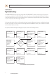
SECTION 3: SYSTEM SETUP Typical video adapter cable Additional network card Video In CH17 - CH32 (AH only) Video In CH1 - CH16 (AH only) RS485 Terminals: Tx + TX RX + RX - Sensors and Control Terminals Audio In CH9 - CH16 Audio In CH1 - CH8 Control 1 Control 2 Control 3 Control 4 Ground Sensor 1 Sensor 2 Sensor 3 Sensor 4 Ground OptiPlex 990 expansion slots (AH series systems) Video In CH9 - CH16 Audio In CH3 - CH4 (PH only) Video In CH1 - CH8 Audio In CH1 - CH2 (PH only) Sensor 1 Ground Sensor 2 Gr
SECTION 3: SYSTEM SETUP Power Self-Test Button Power Status LED Cover Release Latch Security Cable Slot Expansion Slots Back Panel Connectors Power Cable Connector OptiPlex XE backpanel (EH, EI series systems) Output 1 Output 2 Ground Input 1 Input 2 Input 3 Input 4 Ground TRX + TRX − RX + RX − Video In DVI Connector (EH only) Audio Input CH1 - CH4 (bottom to top) (EH30 only) OptiPlex XE expansion slots (EH series systems) The OptiPlex XE chassis EI series system has no expansion cards. 2.
SECTION 3: SYSTEM SETUP Make I/O connections Make connection to sensors (input), relays (output) and an RS485 trunk as needed (see connector diagrams above). When selecting the wire size and color for these connections, follow local codes. Sensor inputs can be configured in the DIGIOP Core software to trigger recording of one camera or more cameras. Sensors and relays can be normally open (NO) or normally closed (NC) type devices. RS485 terminals (TRX +/–, RX +/–) provide a 4-wire RS485 interface. 3.
SECTION 3: SYSTEM SETUP NVR server desktop display 2. Click the clock and date entry in the lower-right corner (system tray) of the desktop. Click Change Date and time settings.., then use the accepted Windows 7 system procedure to configure your server with the local time and time zone. 3. Use the accepted Windows 7 system procedure to configure the network settings of you NVR. 4. Skip to the next subsection of this manual. 3.8.
SECTION 3: SYSTEM SETUP Typical DIGIOP® hDVR multi-image display with no video channels active 2. Click the LOG IN button (in the lower right corner of screen). 3. Enter a User name and Password in the pop-up window, and then click OK. The Administrator default User name and Password are admin and admin. When the login is successful, the LOG IN button label changes to TOOLS. Input password 4. Double click the clock on the upper right corner of the Kiosk window. 5.
SECTION 3: SYSTEM SETUP 7. Click the TOOLS button in the lower right corner of the window, then click Configure in the pop-up menu. 8. In the Configure window, click the Network tab. 9. In the Network frame, click the Edit button to open the Network Settings window. 16 www.digiop.
SECTION 3: SYSTEM SETUP 10. Configure the preferred network settings in the IP Address, Gateway, and DNS frames, then click OK. NOTE 11. To access the Internet from the system, you must define a DNS server. Contact your system administrator for more information. Verify that the Ethernet LAN cable is attached to your hDVR. 3.9 Configuring analog cameras (AH, EH, PH systems only) Analog cameras are automatically added to the hDVR system.
SECTION 3: SYSTEM SETUP 2. Click TOOLS > Configure > Cameras to open the Camera tab. 3. Click the camera icon for the camera channel for which you want to enable audio. In the example shown below, camera channel 1 was selected. Camera Channel Icons 4. Click the Enable Audio checkbox to select it. 5. Click the Close button at the bottom of the window. 18 www.digiop.
SECTION 3: SYSTEM SETUP 6. If in Step 1 you selected Pause Recording, click TOOLS > Start Recording. Otherwise, skip this step. 7. Repeat this procedure for each analog camera channel for which you want to enable audio. 3.9.1 Naming a camera channel The camera channel can be assigned a name that appears on the video image. To rename a camera channel: 1. Click TOOLS > Configure to open the configuration (Preferences) window. By default, 2. If the camera menu is not shown, click the Camera tab. 3.
SECTION 3: SYSTEM SETUP 6. After selecting the new camera name, click the Input button in the keyboard window. The keyboard window will close. 7. To save the entry, click Close in the Camera tab. 3.10 Add IP cameras to the NVR/hDVR IP cameras are added to the NVR/hDVR and configured through the DIGIOP® Control interface.
SECTION 3: SYSTEM SETUP 2. In the Welcome window, enter your assigned Username, Password, and Customer name. The default administrative username/password for NVRs and hDVRs is admin/admin. For local login, the customer name should be digiop. 3. Click Login. After a successful log on, the NVR/hDVR Home page will appear.
SECTION 3: SYSTEM SETUP After a camera is added to the NVR/hDVR, the entry for the IP address under Channel Number shows the channel the camera is assigned to. 3. In the Add a Camera frame, find the IP address of the camera you want to add, then click the associated select action link. The camera will be added to the system and automatically assigned to a camera channel in the NVR or hDVR. 4. Repeat this procedure to add additional cameras to the NVR/hDVR as needed. 5.
SECTION 3: SYSTEM SETUP ADD AN IP CAMERA NOT AUTOMATICALLY DISCOVERED To add an IP camera to the NVR/hDVR that was not automatically discovered on the network: 1. Click the new action link in the Add a Camera pane. New Camera Action Link 2. In the Camera settings list, select the brand from the drop-down list, then enter the remaining settings as needed. 3. Click Save to update the video server with the new IP camera.
SECTION 3: SYSTEM SETUP 1. In the list of cameras added to the video server, click the entry for the camera you want to edit, then click the Edit button at the top of the Home page. 2. In the settings list at the right, change the items as needed. 3. Click Save to update the video server. VIEWING VIDEO FROM YOUR CAMERAS To view video from your cameras, install and configure DIGIOP® Connect. See Setup DIGIOP® Connect software later in this guide. 3.
SECTION 3: SYSTEM SETUP 1. Place a check mark in the Enable Sensors and Controls checkbox. 2. Select a sensor from the list of those that are available. Sensors are color coded to indicate their availability: —— —— —— Blue – Sensor available Yellow – Sensor selected Grey – Sensor unavailable NOTE In this example, an NVR is configured with 16 cameras, four sensor inputs, and four control outputs. 3. Enable sensors by selecting a Sensor Time: From hour and To hour (0-24). 4.
SECTION 3: SYSTEM SETUP 5. After selecting a sensor, you can set up a control (relay output) to activate. 6. Select a Sensor Recording Time: —— —— Sensor Active Duration – Camera records while the sensor is activated Predefined Time – Allows you to record from 3 seconds to 5 minutes (fixed duration) after a sensor is activated. NOTE For comprehensive scheduling of sensor monitoring, go to TOOLS > Configure > Schedule. ASSOCIATING PTZ PRESETS WITH SENSORS 1. Select a sensor. 2.
SECTION 3: SYSTEM SETUP 1. Click TOOLS > Pause Recording if it appears in the menu, then click OK in the Warning window. Pause Recording only appears in the menu if the hDVR is recording. 2. Click TOOLS > Configure > Schedule to open the record scheduling configuration window shown below. Select: Use Schedule Select: Camera 1 Set all timeslots to preferred recording mode Click to Set Selected Timeslots to Sensor Activated Recording 3.
SECTION 3: SYSTEM SETUP COPYING A CAMERA SCHEDULE Once a schedule is defined, you can copy it to other cameras by clicking the Copy To button. The Copy Schedule screen appears. 1. Click the cameras (or All) you want to copy this schedule to. You can later refine each camera schedule by clicking on the camera and changing the schedule. 2. Click the OK button to apply the same schedule to the camera in Room 2 and to close the Copy Schedule window. 3.
SECTION 3: SYSTEM SETUP Export configuration 3. In the Export/Import frame in lower-right corner of the System tab, click Export. 4. Follow the on-screen instructions to identify the location where the export file will be saved. NOTE 6. The DIGIOP® system configuration file is usually smaller than 50KB. It is named: DIGIOPIPDEVICELIST.DVR Wait until the message “Export successfully completed ...” appears before continuing. 3.
SECTION 3: SYSTEM SETUP For more information about DIGIOP® Connect, refer to the DIGIOP® Connect Software User Manual or the DIGIOP® Connect Software Quick Start Guide 3.12.1 Install DIGIOP® Connect DIGIOP® Connect is provided on the Application disk included with your NVR or hDVR hardware. 1. Insert the Application disk into a DVD drive on your computer and find the DIGIOP_ConnectInstallerFull.exe file. Double click or Run this file to start the installation. 2.
SECTION 3: SYSTEM SETUP Source Management Tab View 4. Enter the server configuration fields with the information necessary to identify your source. It may include: —— —— —— —— —— —— —— IP Address or Hostname – This is the IP address or the host name of the video or data server . Username – This is the username that is to be used to access the video or data server. Password – This is the password associated with Username. Port – (Visible for data servers only.
SECTION 3: SYSTEM SETUP 5. Click Save to connect to the DVR or Data Server. 6. If the Name of the system is not displayed in the left panel Systems list, click the Configuration tab, then click Refresh. Example List of Systems 7. 32 To open a connection to the video or data you added, double-click the Name in the Systems list. www.digiop.
SECTION 3: SYSTEM SETUP Example showing three cameras on a Live tab 3.12.3 Add additional video and data servers to DIGIOP® Connect 1. In the DIGIOP® Connect main window, click the Configuration tab, then click the down arrow on the Add icon and select DIGIOP® Video Server. 2. Enter the configuration fields with the information necessary to identify your video or data server as you did for the initial server setup.
APPENDIX A: FAQ APPENDIX A FAQ QQ I cannot see video from my camera at the DVR (NVR or hDVR). What can I do to restore the video? AA First, test the connection to the device using the IPAdmin Tool. Can you see all the cameras on your network with this utility? —— —— YES – The LAN and power to the camera is probably OK. NO – Check the LAN cable, Ethernet signal, and power at the camera. If faulty, correct the problem and recheck the video streaming. Reset the camera. See Appendix B, Camera reset.
APPENDIX B: TROUBLESHOOTING DIGIOP® BLACK IP CAMERA APPENDIX B Troubleshooting DIGIOP® Black IP Cameras B.1 IP Camera reset NOTE The BLK-IPD101 camera does not have a hardware Reset button. To reset the camera while it is in use: NOTE The reboot process lasts about 2 minutes, during which time the camera will not respond to the IPAdmin Tool or transmit video to a web browser The camera can be rebooted in two ways: • • Using the IPAdmin Tool: a. Start the IPAdmin Tool. b.
APPENDIX B: TROUBLESHOOTING DIGIOP® BLACK IP CAMERA —— —— —— —— —— IP address – reset to 192.168.0.100 Subnet mask – reset to 255.255.0.0 Gateway – reset to 192.168.0.1 User ID – reset to root Password – reset to pass To force the camera to the factory network settings: 1. Disconnect the power (adapter) from the camera. 2. While pressing and holding down the reset button, power on the camera. 3. Release the Reset button 5 seconds after applying power. 4. Wait for the camera to reboot. B.2.
APPENDIX C: POWER OVER ETHERNET APPENDIX C Power over Ethernet Some DIGIOP Black cameras and encoders support Power over Ethernet (PoE) in conformance with the IEEE 802.3af standard. IEEE 802.3af allows for two power options for Category 5 (Cat5) cables. The PoE module signature and control circuit provides the PoE compatibility signature and power classification required by the Power Sourcing Equipment (PSE) before applying up to 15 W power to the port.
APPENDIX D: CONFIGURE THE DIGIOP® BLACK IP CAMERA ADDRESS APPENDIX D Configure the DIGIOP® Black IP Camera Address D.1 Install IPAdmin Tool The IPAdmin Tool, included on the CD mini disk, is a utility that will discover cameras installed on your network and enable you to perform the initial network setup for each camera.
APPENDIX D: CONFIGURE THE DIGIOP® BLACK IP CAMERA ADDRESS D.3 Configuring the camera network settings NOTE In networks with a DHCP server, the IP camera will acquire dynamic (changeable) network settings when it is initially powered on. These dynamic settings can easily be converted to static settings, or changed to other static settings that are also compatible with your network. 1. Connect your camera to the network, then power on the camera. 2.
APPENDIX D: CONFIGURE THE DIGIOP® BLACK IP CAMERA ADDRESS 4. In the IP Setup window, click the Static option bullet to select this option. Static Option If you have other compatible, network settings you want to apply to the device, enter them in the appropriate locations. Click Setup to save settings. 5. In the Login window, enter the ID and PW (password) for your camera and click Login. The default administrator values for the ID and PW are root and pass.
APPENDIX D: CONFIGURE THE DIGIOP® BLACK IP CAMERA ADDRESS NOTE To load these ActiveX controls, you may need to adjust the security settings of your browser to accept add-ins from unknown publishers. Typical initial camera view NOTE If, after logging into your camera, you cannot see live video and the message: “Can not Create XMLDOMDocument Install MSXML4.0” appears, download and install the MS XML 4.0 library. This library can be found at: http://www.microsoft.com/downloads/details.
APPENDIX E: DEVICE LOG APPENDIX E Device Log The following table is provided as an aid to setting up and logging the IP devices on your network. 42 NVR/hDVR Description/SKU MAC address IP Address Subnet Mask Gateway Location IP Device Summary www.digiop.
APPENDIX E: DEVICE LOG Analog Camera Device Summary hDVR Channel Camera Model Audio (Y/N) Location 1 2 3 4 5 6 7 8 9 10 11 12 13 14 15 16 NVR and hDVR Systems Setup Guide 43