
User manual


6
www.digiop.com
SECTION 2: INSTALLATION AND SETUP
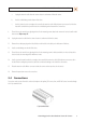
NOTE: When connecting leads from external devices
to the terminal block, use the pin denitions shown on
the circuit board as a guide. Pin denitions on the circuit
board may be dierent from those shown below.
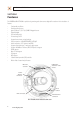
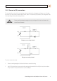
Terminal block pin assignments
NOTE
The terminal connections do not support analog video output.
The 11-pin terminal block may be detached from the camera. Install the block in the location shown above.
2.4.1 Audio in/out connections
The camera includes an interface for a mono audio input (from a microphone) and a mono audio output (to a speaker). The audio
output is a low level signal that requires an amplied speaker (see Specications). The conguration of the audio wiring (Aout, Ain)
is shown in the diagram below.
Audio in/out wiring schematic
To connect a speaker and/or microphone to the camera:
1. Route speaker and/or microphone wiring through the cable channel and into the camera base housing.
2. Strip 1/4” of insulation from the wires and insert them into the terminal block in the locations shown connector terminal
gure above. The common (ground) leads to the microphone and speaker share the same terminal block pin.