H.264 Megapixel Indoor/Outdoor Dome IP Camera User Manual Product: BLK-IPD105M Please read this manual before using your camera, and always follow the instructions for safety and proper use. Save this manual for future reference.
CAUTION Do not operate this camera in environments where the temperatures or humidity is outside the recommended range. Doing so my cause electric shock and shorten the life of the product. LEGAL NOTICE DIGIOP products are designed to meet safety and performance standards with the use of specific DIGIOP authorized accessories. DIGIOP disclaims liability associated with the use of non-DIGIOP authorized accessories.
Table of Contents SECTION 1 SECTION 2 SECTION 3 APPENDIX A APPENDIX B APPENDIX C Features. . . . . . . . . . . . . . . . . . . . . . . . . . . . . . . . . . . . . . . . . . . . . . . . . . . . . . . . . . . . . . . . . . . . . . . . . . . . 2 Installation and Setup. . . . . . . . . . . . . . . . . . . . . . . . . . . . . . . . . . . . . . . . . . . . . . . . . . . . . . . . . . . . . . . . 3 2.1 What’s in the box . . . . . . . . . . . . . . . . . . . . . . . . . . . . . . . . . . . . . . . . . . . . . .
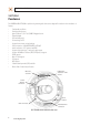
SECTION 1: FEATURES SECTION 1 Features The DIGIOP Black BLK-IPD105M is a professional, premium-grade dome camera designed for outdoor or indoor installation. It features: • • • • • • • • • • • • • • • • • Fixed vandal-proof dome Gimbal mounted camera Aptina™ (Micron™) 1/3.2” (4:3) CMOS 2 Megapixel sensor Digital day/night Dual streaming mode De-interlacing on DSP Supports burnt-in text, unicast/multicast Video compression: H.264/MPEG/MJPEG, 30FPS@D1 Audio compression: G.
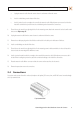
SECTION 2: INSTALLATION AND SETUP SECTION 2 Installation and Setup 2.1 What’s in the box Your dome camera includes the following: • • • • • • • BLK-IPD105M camera DC power adapter with power plugs for different powering sources Base seal (surface cushion) Power extension cable 11-pin terminal block Hardware installation kit with a hex wrench, 3 screws and wall inserts CD mini disk with application software and documentation 2.
SECTION 2: INSTALLATION AND SETUP Camera dome removal 3. Using the base as a template, mark the location of the three mounting screw holes. 4. Drill mounting screw holes into the mounting surface: —— —— —— If the mounting surface is a soft material, such as a drywall, drill and install drywall inserts for the mounting screws.
SECTION 2: INSTALLATION AND SETUP a. Unplug the extension cable from the camera electronics and remove it from the camera. b. Install a conduit fitting onto the bottom of the base. c. Install a junction box close enough to the camera for the extension cable LAN and power connectors to be in the box. Attach the conduit for the junction box to the conduit fitting on the bottom of the camera base. 9. Place the base seal over the base, aligning the holes for the mounting screws.
SECTION 2: INSTALLATION AND SETUP NOTE: When connecting leads from external devices to the terminal block, use the pin definitions shown on the circuit board as a guide. Pin definitions on the circuit board may be different from those shown below. Terminal block pin assignments NOTE The terminal connections do not support analog video output. The 11-pin terminal block may be detached from the camera. Install the block in the location shown above. 2.4.
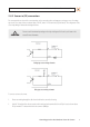
SECTION 2: INSTALLATION AND SETUP 2.4.2 Sensor in (DI) connection The camera provides one channel for sensor input that can be connected to either a voltage type or relay type sensor. For voltage type sensors, the camera allows a maximum input of 24 V DC, with a 1 V DC threshold (see Specifications). The configuration of the sensor input wiring is illustrated in the diagrams below. CAUTION Do not exceed the maximum input voltage or the relay switching rate.
SECTION 2: INSTALLATION AND SETUP 2.4.3 Alarm out (DO) connection The camera supports one alarm out connection to relay type device. It provides up to 24 V AC @ 500 mA or 12 V DC @ 1 A. The configuration of the relay type alarm wiring is illustrated in the diagram below. CAUTION Do not exceed the maximum relay rating. Refer to the specifications in this manual for more information. Relay type alarm wiring schematic To connect an alarm reporting device to the camera: 1.
SECTION 2: INSTALLATION AND SETUP To connect an RS-485 device wiring to the camera: 1. Route RS-485 device wiring through the cable channel and into the camera base housing. 2. Strip 1/4” of insulation from the wires and insert them into the terminal block. Observe the signal polarity shown in the schematic. 2.4.5 LAN and power connections 1. Route a LAN drop cable into the camera and plug it into the RJ-45 LAN connector. Power connector LAN connector 2.
SECTION 2: INSTALLATION AND SETUP 2.5 Install IPAdmin Tool The IPAdmin Tool, included on the CD mini disk, is a utility that will discover cameras installed on your network and enable you to perform the initial network setup for each camera. After a camera is setup on the network, the Microsoft Internet Explorer ® web browser can be used to see video from the camera, set the camera’s password, date and time, finalize camera hardware adjustments, and configure the camera for functional requirements.
SECTION 2: INSTALLATION AND SETUP ensure that your camera won’t conflict with other devices. Your network administrator should also setup WAN (Internet) access to the camera, if that is needed. If you encounter a problem and need to contact Technical Support, first complete the chart in Table 1 about your computer (PC) and camera network settings, if possible. Support will need this information to provide assistance. 2.6.
SECTION 2: INSTALLATION AND SETUP 4. In the IP Setup window, click the Static option bullet to select this option. Static Option If you have other compatible, network settings you want to apply to the device, enter them in the appropriate locations. Click Setup to save settings. 5. In the Login window, enter the ID and PW (password) for your camera and click Login. The default administrator values for the ID and PW are root and pass. After entering ID and PW, the IP Setup window closes. 6.
SECTION 2: INSTALLATION AND SETUP 2.6.2 Configuring cameras on networks without DHCP NOTE The following procedure works with most networks. For further assistance, contact Technical Support. Cameras installed on a network without a DHCP server will initially use the factory default static network settings: IP address: Subnet mask: Gateway: 192.168.0.100 255.255.255.0 192.168.0.
SECTION 2: INSTALLATION AND SETUP Example: Typical use of ipconfig in Windows XP d. Enter the IP Address, Subnet Mask, and Default Gateway for your PC’s Ethernet adapter into Table 1. The Ethernet adapter data you see by using ipconfig will probably be different from that shown in the example above. If you are using Windows Vista or Windows 7, the IP address is identified as the “IPv4 Address.” NOTE Table 1.
SECTION 2: INSTALLATION AND SETUP c. Next, use the ping command in the DOS window to see if this IP address is in use on your network. The format of the ping command is: ping To test this IP address, enter ping 192.168.1.200. Any reply received from the ping indicates that a device on the network is already using this IP address and you can connect to it. In the example shown above, the message “Reply from 192.168.1.200: ..
SECTION 2: INSTALLATION AND SETUP At a Microsoft Windows computer attached to the LAN subnet where the camera will be connected, open a Command Prompt window and enter: ping 192.168.0.100 The “Request timed out” response indicates that the IP address is not in use and the camera can be connected without causing errors. Attach your camera to the network and power it on Apply power to the camera. When the camera powers on, it performs an internal initialization, then establishes a connection to the LAN.
SECTION 2: INSTALLATION AND SETUP 3. Right click on the entry for your camera and select IP Address. IP Setup window 4. In the IP Setup window: a. Select the Static option if it is not selected. This option is required if video from the camera will be recorded by a network DVR, or if you want to view video from the camera across a WAN (Internet). b. Enter the IP address for your camera from Table 1 into the IP Address field. c.
SECTION 2: INSTALLATION AND SETUP 1. Open the IE browser. 2. In the URL field (Internet address), enter the IP address for your camera in the format: http:/// where is the IP address of your camera. Following the example earlier in this guide, the entry would be: http://192.168.1.201 3. If prompted to install an ActiveX control such as AxAll.cab (publisher Cap Co), follow screen prompts to install the software.
SECTION 2: INSTALLATION AND SETUP NOTE If, after logging into your camera, you cannot see live video and the message: “Can not Create XMLDOMDocument Install MSXML4.0” appears, download and install the MS XML 4.0 library. This library can be found at: http://www.microsoft.com/downloads/details.aspx?familyid=3144B72B-B4F2-46DA-B4B6-C5D7485F2B42&displaylang=en 4. In the camera window, click the SETUP link in the upper right corner of the window.
SECTION 2: INSTALLATION AND SETUP c. Select the Sync Source and Interval you prefer. d. Click Apply. 6. In the Basic Configuration menu, click Users. 7. In the User List, click root, and then click Modify and follow the prompts. Setup the administrator user with a new password and click OK. 8. In the Users menu, click Apply, then click OK to restart the webserver (if you wish to do so at this time). 9. Click Add to include other administrators, operators or viewers to the user list.
SECTION 2: INSTALLATION AND SETUP 2.8 Aim, focus, and image quality adjustment 2.8.1 Aim The camera mount allows the camera to be rotated on three axis to set the horizon alignment, horizontal direction, and up/down position of the video frame. Horizon alignment Horizontal direction Up/down position Lens shroud 1. Gently lift the lens shroud off the camera assembly to remove it from the camera assembly. 2.
SECTION 2: INSTALLATION AND SETUP 2.8.3 Image quality adjustments Adjustments to the image brightness, contrast, hue, saturation, and sharpness are performed through the web browser: 1. From the VIEW window, click: SETUP > Video & Audio > Video-In 2. Scroll to the bottom of the screen and click the PREVIEW button. Follow the screen instructions to open the camera view in another IE window. 3.
SECTION 2: INSTALLATION AND SETUP 2. On the VIEW screen, click: SETUP > Video & Audio > Audio to open the Bi-directional Audio Settings menu. 3. In the Bi-directional Audio Settings menu, click the checkboxes to select “Listen to the audio from server with setting below” and “Talk to the speakers of server”. 4. Click Apply, and then click VIEW to return to the camera view screen. 5.
SECTION 2: INSTALLATION AND SETUP 2.10 Cleaning Clean the camera housing with an approved glass cleaning solution and a lint free cloth. • • Dust can be removed from the unit by wiping it with a soft damp cloth. To remove stains, gently rub the surface with a soft cloth moistened with a mild detergent solution, then rinse and dry it with a soft cloth. Remove all foreign particles, such as plastic or rubber materials, attached to the camera housing. These may cause damage to the surface over time.
SECTION 3: SPECIFICATIONS SECTION 3 Specifications Table 2. Specifications Camera Module CMOS ELECTRICAL Image Sensor Aptina (Micron) 1/3.2” (4:3) CMOS 2 Megapixel Effective Pixels 1600 x 1200 (UXGA, 2M) Scanning system Progressive Resolution 550 TV lines SNR 71 dB Min. Illumination 0.5 Lux (50IRE), 0.1 Lux (DSS x5 ON) Wide Dynamic Range 52 dB (x128) Color ON/AUTO AGC Control AUTO White Balance AUTO Electronic Shutter Speed AUTO Lens 3.3~12 mm, F1.6~3.
SECTION 3: SPECIFICATIONS Resolution (Compression FPS. NOTE: FPS may be decreased if using burnt-in text or VCA.) H.264 5 fps @ UXGA (1600 x 1200) 8 fps @ SXGA (1280 x 1024) 12 fps @ HD720 (1280 x 720) 15 fps @ XGA (1024 x 768), D1 (720 x 480) MJPEG 15 fps @ UXGA (1600 x 1200) MPEG–4 15 fps @ D1 (720 x 480) Motion Detection Supported Burnt-in Text (Digital) Supported (DSP) Output Not supported Audio Input/output 1/1 channel Compression Format G.
SECTION 3: SPECIFICATIONS Table 3. Video Content Analysis (optional) VCA Presence High Performance Advanced Tracking Algorithm, Low False Alarm Rate Easy to Use Intuitive Web Browser Interface Detection Zones Multi-segment Polygons and Lines On-screen Display Real-time Display of Tracking Data and Events Burnt-in Annotation Stream out Image Stabilization Electronic Stabilization Removes Camera Sway H.
APPENDIX A: TROUBLESHOOTING APPENDIX A Troubleshooting A.1 Reboot camera NOTE The reboot process lasts about 2 minutes, during which time the camera will not respond to the IPAdmin Tool or transmit video to a web browser The camera can be rebooted in two ways: • • Using the IPAdmin Tool: a. Start the IPAdmin Tool. b. Find the entry for the camera you want to reboot and click it to select (highlight) it. c. Click the Reboot button and enter the administrator ID and PW. d.
APPENDIX A: TROUBLESHOOTING To force the camera to the factory network settings: 1. Disconnect the power (adapter) from the camera. 2. While pressing and holding down the reset button, power on the camera. 3. Release the Reset button 5 seconds after applying power. 4. Wait for the camera to reboot. A.3 Checking your Firmware Firmware is software embedded in the camera that determines many of its features and functionality.
APPENDIX B: DIMENSIONS APPENDIX B Dimensions 5.94” Top View Ø 3.94” 4.47” 3/4” Tap Side View 30 www.digiop.
APPENDIX B: DIMENSIONS 1.24” 3/4” Tap Ø 4.53” ~ Ø .15” Base view H.
APPENDIX C: POWER OVER ETHERNET APPENDIX C Power over Ethernet The BLK-IPD105M camera supports Power over Ethernet (PoE) in conformance with the IEEE 802.3af standard. IEEE 802.3af allows for two power options for Category 5 cables. The PoE module signature and control circuit provides the PoE compatibility signature and power classification required by the Power Sourcing Equipment (PSE) before applying up to 15 W power to the port.