H.264 Indoor/Outdoor Dome IP Camera User Manual Product: BLK-IPD104 Please read this manual before using your camera, and always follow the instructions for safety and proper use. Save this manual for future reference.
CAUTION Do not operate this camera in environments where the temperatures or humidity is outside the recommended range. Doing so my cause electric shock and shorten the life of the product. LEGAL NOTICE DIGIOP® products are designed to meet safety and performance standards with the use of specific DIGIOP authorized accessories. DIGIOP disclaims liability associated with the use of non-DIGIOP authorized accessories.
Table of Contents SECTION 1 SECTION 2 SECTION 3 APPENDIX A APPENDIX B APPENDIX C Features. . . . . . . . . . . . . . . . . . . . . . . . . . . . . . . . . . . . . . . . . . . . . . . . . . . . . . . . . . . . . . . . . . . . . . . . . . . . 2 Installation and Setup. . . . . . . . . . . . . . . . . . . . . . . . . . . . . . . . . . . . . . . . . . . . . . . . . . . . . . . . . . . . . . . . 3 2.1 What’s in the box . . . . . . . . . . . . . . . . . . . . . . . . . . . . . . . . . . . . . . . . . . . . . .
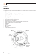
SECTION 1: FEATURES SECTION 1 Features The DIGIOP Black BLK-IPD104 is a professional, premium-grade dome camera designed for outdoor or indoor installation. It features: • • • • • • • • • • • • • • • • • Fixed vandal-proof dome Gimbal mounted camera Sony® 1/3” Super HAD CCD sensor and High Quality SS-HQ1 full kit chipset True day/night ICR and WDR Dual streaming mode De-interlacing on DSP Supports burnt-in text, unicast/multicast Video compression: H.264/MPEG-4/MJPEG 30 fps @ D1 Audio compression: G.
SECTION 2: INSTALLATION AND SETUP SECTION 2 Installation and Setup 2.1 What’s in the box Your dome camera includes the following: • • • • • • • BLK-IPD104 camera DC power adapter with power plugs for different powering sources Base seal (surface cushion) Power extension cable 11-pin terminal block Hardware installation kit with a hex wrench, 3 screws and wall inserts CD with application software, software manual, and camera documentation 2.
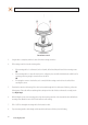
SECTION 2: INSTALLATION AND SETUP Camera dome removal 3. Using the base as a template, mark the location of the three mounting screw holes. 4. Drill mounting screw holes into the mounting surface: —— —— —— If the mounting surface is a soft material, such as a drywall, drill and install drywall inserts for the mounting screws.
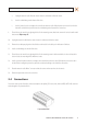
SECTION 2: INSTALLATION AND SETUP a. Unplug the extension cable from the camera electronics and remove it from the camera. b. Install a conduit fitting onto the bottom of the base. c. Install a junction box close enough to the camera for the extension cable LAN and power connectors to be in the box. Attach the conduit for the junction box to the conduit fitting on the bottom of the camera base. 9. Place the base seal over the base, aligning the holes for the mounting screws.
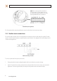
SECTION 2: INSTALLATION AND SETUP NOTE: When connecting leads from external devices to the terminal block, use the pin definitions shown on the circuit board as a guide. Pin definitions on the circuit board may be different from those shown below. Terminal block pin assignments The 11-pin terminal block may be detached from the camera. Install the block in the location shown above. 2.4.
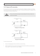
SECTION 2: INSTALLATION AND SETUP 2.4.2 Sensor in (DI) connection The camera provides one channel for sensor input that can be connected to either a voltage type or relay type sensor. For voltage type sensors, the camera allows a maximum input of 24 V DC, with a 1 V DC threshold (see Specifications). The configuration of the sensor input wiring is illustrated in the diagrams below. CAUTION Do not exceed the maximum input voltage or the relay switching rate.
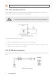
SECTION 2: INSTALLATION AND SETUP 2.4.3 Alarm out (DO) connection The camera supports one alarm out connection to relay type device. It provides up to 24 V AC @ 500 mA or 12 V DC @ 1 A. The configuration of the relay type alarm wiring is illustrated in the diagram below. CAUTION Do not exceed the maximum relay rating. Refer to the specifications in this manual for more information. Relay type alarm wiring schematic To connect an alarm reporting device to the camera: 1.
SECTION 2: INSTALLATION AND SETUP To connect an RS-485 device wiring to the camera: 1. Route RS-485 device wiring through the cable channel and into the camera base housing. 2. Strip 1/4” of insulation from the wires and insert them into the terminal block. Observe the signal polarity shown in the schematic. 2.4.5 Video out connection The camera provides pins on the terminal block to attach a local video monitor. A cable extension with a BNC connector is included in the packaging with the camera.
SECTION 2: INSTALLATION AND SETUP 2. Route the wire end of the power extension cable into the camera and connect it to the 12 VDC power connector. 3. Connect the other end of the power extension cable to the DC12V power adapter. The polarity of the adapter connector is shown in the following diagram. DO NOT apply power to the camera at this time. CAUTION When applying power to the camera, ensure that the polarity is correct. An incorrect connection may cause a malfunction and can damage the camera.
SECTION 2: INSTALLATION AND SETUP When your IP camera is attached to a network and initially powered on, it attempts acquire compatible network settings from a DHCP server. If it cannot find a DHCP server, it configures itself with the following static IP address, subnet mask, and gateway setting, which may or may not be compatible with other devices on the network. IP address: Subnet mask: Gateway: 192.168.0.100 255.255.255.0 192.168.0.
SECTION 2: INSTALLATION AND SETUP Check the list of IP devices found by IPAdmin Tool. You can identify your camera by the MAC address. If the camera was not found, click the Refresh button every minute until your camera appears in the list. 3. In the IPAdmin Tool device list, use the camera’s MAC Address to find the camera you are installing. After finding the camera, right click the entry, then select IP Address from the drop-down list. An IP Setup window will open. 4.
SECTION 2: INSTALLATION AND SETUP If you have other compatible, network settings you want to apply to the device, enter them in the appropriate locations. Click Setup to save settings. 5. In the Login window, enter the ID and PW (password) for your camera and click Login. The default administrator values for the ID and PW are root and pass. After entering ID and PW, the IP Setup window closes. 6.
SECTION 2: INSTALLATION AND SETUP b. Type cmd in the entry field, then click OK to open the DOS command window. c. At the command prompt, enter ipconfig. The response will show the your PC’s network settings. Example: Typical use of ipconfig in Windows XP d. Enter the IP Address, Subnet Mask, and Default Gateway for your PC’s Ethernet adapter into Table 1. NOTE The Ethernet adapter data you see by using ipconfig will probably be different from that shown in the example above.
SECTION 2: INSTALLATION AND SETUP Find network settings (IP addresses) that are not in use 1. At your PC, find an IP address on your network that is not in use: a. Write down the EXACT IP address of your PC up to the third/last period. Using the example shown above, this expression is: 192.168.1. b. After the third period, include any number between 1 and 254 that is different from the one in your PC’s IP address, 168. As a first try, let’s choose 200, which will form the IP address 192.168.1.200. c.
SECTION 2: INSTALLATION AND SETUP e. In this test, the message “Request timed out” indicates that your PC cannot reach the device with that IP address, and that address is probably not in use. Enter this number into Table 1. If this test indicated that this IP address is in use, try other IP addresses using the steps above until an unused address is found. Check LAN for default IP address compatibility Because all DIGIOP Black cameras and encoders are factory configured with the static IP address 192.
SECTION 2: INSTALLATION AND SETUP 2. In the Product list, find the entry with the same MAC address as the camera you installed. If the camera is not shown, click Refresh once a minute to update the list. 3. Right click on the entry for your camera and select IP Address. IP Setup window 4. 5. In the IP Setup window: a. Select the Static option if it is not selected.
SECTION 2: INSTALLATION AND SETUP 6. In the IPAdmin Tool window, click Refresh and verify that the entry representing the camera now shows the new IP address. 7. In the IPAdmin Tool window, click Refresh and verify that the entry for your camera now shows the new IP address. 2.7 Setup the camera Basic Configuration IIn this procedure, use the Internet Explorer (IE) browser to setup the camera administrator and user passwords, date, and time. 1. Open the IE browser. 2.
SECTION 2: INSTALLATION AND SETUP Typical initial camera view NOTE If, after logging into your camera, you cannot see live video and the message: “Can not Create XMLDOMDocument Install MSXML4.0” appears, download and install the MS XML 4.0 library. This library can be found at: http://www.microsoft.com/downloads/details.aspx?familyid=3144B72B-B4F2-46DA-B4B6-C5D7485F2B42&displaylang=en 4. In the camera window, click the SETUP link in the upper right corner of the window.
SECTION 2: INSTALLATION AND SETUP In the Date & Time Setting options: 6. 20 a. Select the Time Zone you prefer. b. Select the synchronization method, or Set Manually bullet and enter the appropriate information. c. Select the Sync Source and Interval you prefer. d. Click Apply. In the Basic Configuration menu, click Users. www.digiop.
SECTION 2: INSTALLATION AND SETUP 7. In the User List, click root, and then click Modify and follow the prompts. Setup the administrator user with a new password and click OK. 8. In the Users menu, click Apply, then click OK to restart the webserver (if you wish to do so at this time). 9. Click Add to include other administrators, operators or viewers to the user list. Follow the screen prompts to complete the entries. 10.
SECTION 2: INSTALLATION AND SETUP Horizon alignment Horizontal direction Up/down position Lens shroud 1. Gently lift the lens shroud off the camera assembly to remove it from the camera. 2. While observing video from the camera, set the horizon alignment by rotating camera module bracket on its horizontal axis (direction the lens is pointed). 3. Set the horizontal direction of the video frame by rotating camera assembly on its vertical axis. 4.
SECTION 2: INSTALLATION AND SETUP 2. Scroll to the bottom of the screen and click the PREVIEW button. Follow the screen instructions to open the camera view in another IE window. 3. While observing the video in the PREVIEW window, adjust the values for brightness, contrast, hue, saturation, sharpness, and/or other parameters on screen. Click Apply to see the effect of the change. Make any necessary adjustments to produce the best video image. 4.
SECTION 2: INSTALLATION AND SETUP 3. In the Bi-directional Audio Settings menu, click the check boxes to select “Listen to the audio from server with setting below” and “Talk to the speakers of server”. 4. Click Apply, and then click VIEW to return to the camera view screen. 5. On the VIEW screen, check the SPK and MIC options to enable the speaker at the camera and the microphone on your computer. 6. At your computer, listen for sounds from the microphone at the camera.
SECTION 2: INSTALLATION AND SETUP 2.10 Cleaning Clean the camera housing with an approved glass cleaning solution and a lint free cloth. • • Dust can be removed from the unit by wiping it with a soft damp cloth. To remove stains, gently rub the surface with a soft cloth moistened with a mild detergent solution, then rinse and dry it with a soft cloth. Remove all foreign particles, such as plastic or rubber materials, attached to the camera housing. These may cause damage to the surface over time.
SECTION 3: SPECIFICATIONS SECTION 3 Specifications Table 2. Specifications Camera Module CCD Sync ELECTRICAL Image Sensor SONY 1/3” Super HAD CCD Effective Pixels NTSC: 768(H) x 494(V); PAL: PAL: 752(H) x 582(V) Size 1/3 inch interline transfer CCD Scanning system 2:1 Interlace Frequency NTSC: 15.734 KHz (H) 59.94 Hz(V); PAL:15.625 KHz(H) 50.00 Hz (V) Resolution 550 TV lines S/N (Y signal) 52 dB (AGC Off, weight on) Min. Illumination 0.00001 Lux F1.
SECTION 3: SPECIFICATIONS Function Digital Input/output 1/1 channel RS-485 Supported Network 10/100Base-T Power over Ethernet Supported Protocol TCP/IP, UDP/IP, HTTP, RTSP, RTCP, RTP/UDP, RTP/TCP, SNTP, mDNS, UPnP, SMTP, SOCK, IGMP, DHCP, FTP, DDNS, SSL v2/v3, IEEE 802.1X, SSH, SNMP v2/v3 SD Slot Supported — MicroSD (MicroSD card not included) Material Aluminum Die Casting Dimensions Housing : 5.94”dia. x 4.45”h, Dome : 3.94”dia.
SECTION 3: SPECIFICATIONS Table 3.
APPENDIX A: TROUBLESHOOTING APPENDIX A Troubleshooting A.1 Reboot camera NOTE The reboot process lasts about 2 minutes, during which time the camera will not respond to the IPAdmin Tool or transmit video to a web browser The camera can be rebooted in two ways: • • Using the IPAdmin Tool: a. Start the IPAdmin Tool. b. Find the entry for the camera you want to reboot and click it to select (highlight) it. c. Click the Reboot button and enter the administrator ID and PW. d.
APPENDIX A: TROUBLESHOOTING To force the camera to the factory network settings: 1. Disconnect the power (adapter) from the camera. 2. While pressing and holding down the reset button, power on the camera. 3. Release the Reset button 5 seconds after applying power. 4. Wait for the camera to reboot. A.3 Checking your Firmware Firmware is software embedded in the camera that determines many of its features and functionality.
APPENDIX B: DIMENSIONS APPENDIX B Dimensions 5.94” Top View Ø 3.94” 4.47” 3/4” Tap Side View H.
APPENDIX B: DIMENSIONS 1.24” 3/4” Tap Ø 4.53” ~ Ø .15” Base view 32 www.digiop.
APPENDIX C: POWER OVER ETHERNET APPENDIX C Power over Ethernet The BLK-NewIPE3500L camera supports Power over Ethernet (PoE) in conformance with the IEEE 802.3af standard. IEEE 802.3af allows for two power options for Category 5 cables. The PoE module signature and control circuit provides the PoE compatibility signature and power classification required by the Power Sourcing Equipment (PSE) before applying up to 15 W power to the port.