
Instruction manual

-7-
INSTALLATION. VANDAL DOME
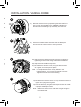
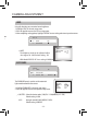
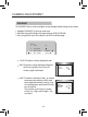
7a) Re-attach the camera cover. Line up arrows as shown in
gure 3a on page 6 as a guide
7b) Use the allen key to tighten the tamper screws to create
a proper weatherproof seal.
Note: Make sure dome cover cord does not get caught in
the rubber seal.
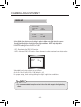
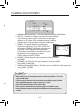
1) Remove the three tamper screws using the provided
allen key. Size is standard T-15
Note: If you plan to use conduit tting, remove conduit
cap using the prodivded conduit key.
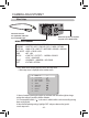
DPV24TLX ONLY
When using DC power, note the correct polarity stated on the
label attached to the power cord.
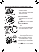
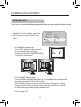
Method 1 - Direct Attach Install
2a) Use included mounting template to mark and pre-
drill the required holes. Use 2pc of the 2.8” screws
to mount the camera directly to the mounting
surface.
Remove (one base locking screw, used for shipping
purposes) and install the 3rd 2.8” screw.
Go to step
4
on page 7 to complete installation.
OR
Method 2 - Camera Base Install
Note: Use this method if installing onto junction box
plate.
2b) Remove the camera base by unscrewing the base
locking screw, and turn camera module approx. 5
degrees counter-clockwise to detach camera base
from the camera module. Now you install the base
to the correct holes as indicated on the mount
template using the 1.2” screws.
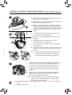
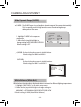
6a) Adjust camera viewing angle and secure into place by
tightening thumb screw using a at head screwdriver.
6b) Adjust lens and OSD as required.
6c) Re-attach the camera cover, using the thumb screw
as a guide, until it snaps into place.
Note: Lens adjustment levers are by default in the
locked position. Turn counter clockwise to unlock.
Tighten levers to secure lens setting.
5) Insert the included video test cable into the RCA jack
and connect to a test monitor to set up camera.
4) Remove camera cover by squeezing the back and front
of the cover as indicated by the “PRESS” indicators at
the same time and lifting it up and away from the lens.
7
5
6
4