INSTRUCTION MANUAL Ultra Resolution Day & Night Dome Camera Vandal Models: DPV24D / DPV24TLX Indoor Models: DPD23D / DPD24D Please read this manual thoroughly before use and keep it handy for future reference.
INTRODUCTION Features All Models Feature: DPD24D • 1/3” Sony Super HAD™ II CCD • Excellent low light performance using Polaris Vision 2 technology. • 0.15 Lux / F1.2 (Color) 0.001 Lux w/Sense-Up at x256 • 600 TV lines(Color) of resolution • 3D Digital Noise Reduction (3D-DNR) • OSD menu control • Privacy Masking / Motion Detection • VIDEO OUT(BNC) • Operates in 12VDC or 24VAC • Test Monitor Output • Camera Mounting: Surface / Flush mounting (Indoor Model only) • Indoor Dome Model • 2.8-10.
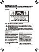
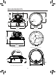
MEASUREMENTS 97.0 mm 3.82 in 55.5 mm 2.19 in 112 mm 4.4 in 3/4’’ -14 NPS thread 40 mm 1.57 in 3.4" 87 mm Ø 0.1" 3.5 mm 5.1" 130 mm 3.9" 100.0 mm Vandal Dome Dimensions Base hole positions 100° 112 mm 4.4 in 137° 123° 5.1" 130 mm Indoor Dome Dimensions 27 mm 1.1 in Underside Base hole positions 39 mm 1.5 in 115 mm 4.5 in Recess Mount Fitting dimensions Recess cutout and fitting clearance. -2- 7 mm .
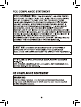
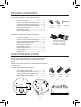
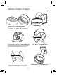
PACKING CONTENTS Indoor Dome package contains the following: Camera in housing----------------------------------1 Camera Locking screws (PA3 Type)------------2 Instruction guide (This Document)--------------1 Surface & Flush Mounting Templates----------2 RCA - BNC test cable-------------------------------1 Junction Box Plate-----------------------------------1 Mounting screw pack-------------------------------1 Locking Screw Conduit Key Allen Key Vandal Dome package contains the following: Camera in hou
JUNCTION BOX INSTALLATION TYPES 2S FITTING a. Screws Cable Entry 2S Fitting requires only 2pcs of base attachment screws. Note: You have a reduced space in which to hide cables using this type of installation. Recommended for indoor dome only. 4S FITTING a. Screws Cable Entry 4S Fitting requires 2pcs of base attachment screws. Note: Screws used for the 4S box are larger compared to those used for the 2S (M4 type). Suitable for both indoor and vandal domes TWO GANG FITTING a.
VANDAL DOME FITTINGS Pendant Cap - model # MNTV2XPC Replaces the need for the camera base. Compatible with ceiling conduit installations Junction Box Accessory - model # MNTV2XJ Fits either wall mount and corner mount bracket. Symmetrical so reversible for top or bottom conduit. Corner Mount bracket - model # MNTV2XR Can fit either Wall Bracket or Junction Box.
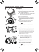
INSTALLATION. VANDAL DOME 1 DPV24TLX ONLY When using DC power, note the correct polarity stated on the label attached to the power cord. 1) Remove the three tamper screws using the provided allen key. Size is standard T-15 Note: If you plan to use conduit fitting, remove conduit cap using the prodivded conduit key. Method 1 - Direct Attach Install 2 2a) Use included mounting template to mark and predrill the required holes. Use 2pc of the 2.8” screws to mount the camera directly to the mounting surface.
ed on the INSTALLATION. VANDAL DOME 4 provided 4) Remove camera cover by squeezing the back and front of the cover as indicated by the “PRESS” indicators at the same time and lifting it up and away from the lens. 5) Insert the included video test cable into the RCA jack and connect to a test monitor to set up camera. e conduit nd prescrews ng 5 pping tion. on box he base prox.
INSTALLATION. INDOOR DOME (Surface Fitting) 1 1a) Press down on the tab marked with an arrow to lift up the dome cover slightly b a 1b) While pressing on tab, twist the dome cover counter clockwise just a few degrees to release dome cover from back clips. Lift off the cover. Method 1 - Direct Attach Install 2 2a) Use included mounting template to mark and predrill the required holes. Use included 2.8” screws to mount the camera directly to the mounting surface.
ow to lift INSTALLATION. INDOOR DOME (Semi-Flush Fitting) 1 1a) Press down on the tab marked with an arrow to lift up the dome cover slightly r ease nd prescrews ng 1b) While pressing on tab, twist the dome cover counterclockwise to release dome cover b a 2 a) Cut semi flush mounting hole into surface using provided flush mounting template. Note: Always cut according to the inside of the cutout template tion.
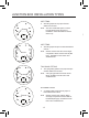
CAMERA ADJUSTMENT Menu Setup RCA Service Connector Use supplied RCA - BNC cable If you require BNC output. OSD function joystick. Pressing down on joystick acts as ENTER function.
CAMERA ADJUSTMENT LENS Using this function, you can control screen brightness. 1. Highlight 'LENS' in the main setup menu 2. Press the joystick to access the DC lens setup menu. 3. After completing setting update, highlight 'RETURN' to save setting and return to previous menu essing down function. e essing SETUP 1. LENS 2. EXPOSURE DC • NOTE The brightness level can be adjusted within the range of 0 - 100.
CAMERA ADJUSTMENT SENSE-UP B EXPOSURE SHUTTER AGC SENSE-UP BLC D-WDR RETURN The 1/60 MIDDLE AUTO OFF OFF RET Select digital slow shutter speed setting in order to allow extra light into the camera thereby providing higher sensitivity in low light conditions. NOTE only adjustable if SHUTTER setting is set to 'AUTO' or '1/60' - OFF : Deactivates the SENS-UP function. - AUTO : Activates SENS-UP function.
ue CAMERA ADJUSTMENT BACKLIGHT (BLC) The BLC menu is used to adjust backlight compensation function to sharpen subjects in backlight situations 1. Highlight 'BLC' in the exposure setup menu. 2. Press the joystick to access the BLC setup menu. EXPOSURE SHUTTER AGC SENSE-UP BLC D-WDR RETURN BLC (Backlight Compensation): Enter the BLC submenu to select an area in the scene which requires enhancing. Change the GAIN value (LOW/MIDDLE/HIGH) to set level of enhancement.
CAMERA ADJUSTMENT Wide Dynamic Range (E-WDR) D-WDR : The D-WDR menu is used to adjust dynamic range of the camera electronically. This is especially useful in high contrast scenes in order to brighten up darker parts of the scene. 1. Highlight 'D-WDR' in the exposure setup menu. 2. Move the the joystick left/right to change setting to OFF/INDOOR/OUTDOOR.
CAMERA ADJUSTMENT SETUP 1. LENS 2. EXPOSURE 3. WHITE BAL 4. DAY NIGHT ronically. peratures. DC AWB AUTO AWB(Automatic White Balance) : This mode automatically adjusts white balance AWC-SET : To obtain the optimum state under the current luminance levels, direct the camera to point toward a sheet of white paper and press the SET button. If the environment changes, including the light source, the white balance will require re-adjustment.
CAMERA ADJUSTMENT DAY/NIGHT The DAY/NIGHT menu is used to configure the day and night related settings for the camera. 1. Highlight 'DAY&NIGHT' in the main setup menu 2. Move the the joystick left/right to change setting to AUTO/COLOR/ B/W 3. Press the joystick to access the submenu's for AUTO and B/W settings SETUP 1. LENS 2. EXPOSURE 3. WHITE BAL 4. DAY NIGHT DC MANUAL AUTO COLOR : The picture is always displayed in color. B/W : The picture is always displayed in black and white.
he camera. CAMERA ADJUSTMENT Digital Noise Reduction (3D DNR) This function reduces the background noise in a low luminance environment. 1.Highlight '3DNR' in the main setup menu. SETUP 1. LENS 2. EXPOSURE 3. WHITE BAL 4. DAY NIGHT 5. 3DNR DC MANUAL AUTO ON 2. Move the the joystick left/right to change setting to OFF/ON OFF - Noise is not reduced ON - Noise is reduced 3. Press the joystick to access the submenu for ON setting.
CAMERA ADJUSTMENT SPECIAL. 1. Highlight 'SPECIAL' in the main setup menu. • SETUP 1. LENS 2. EXPOSURE 3. WHITE BAL 4. DAY NIGHT 5. 3DNR 6. SPECIAL 7. ADJUST 8. RESET 9. EXIT DC • • ATW AUTO ON 2. Press the joystick to access the submenu for SPECIAL settings. SPECIAL 1. 2. 4. 5. 6. 7. 8. 9. CAM TITLE D-EFFECT MOTION PRIVACY SYNC LANGUAGE DEFECT RETURN OFF OFF OFF INT ENG RET • CAM TITLE : If you enter a title, the title will appear on the monitor. 1.
CAMERA ADJUSTMENT Notes • When the CAM TITLE is OFF no title will be displayed on the monitor even if you had previously setup a name. This is the master display setting. • Only English is available in this mode for camera title. • Only max 15 characters for the title allowed. 2. Press the joystick to access the submenu for ON setting. Here you will be able to enter the camera title. CAM TITLE 0123456789 ABCDEFGHIJK LMNOPQRSTUV WXYZ() ¯-_/■=&:~,. CLR POS END 3.
CAMERA ADJUSTMENT D-EFFECT: Applies digital effects to camera image. 1. Highlight 'D-EFFECT' in the SPECIAL setup menu. SPECIAL 1. CAM TITLE 2. D-EFFECT 3. MOTION 4. PRIVACY 6. SYNC 7.access LANGUAGE 2. Press the joystick to the submenu. 8. RETURN OFF OFF OFF INT ENGLISH END D-EFFECT Notes FREEZE MIRROR D-ZOOM NEG.IMAGE RETURN OFF OFF OFF OFF RET 3. FREEZE: Freezes current image displayed 4. MIRROR: MIRROR will mirror the image. V-FLIP, will flip the image vertically.
ky image CAMERA ADJUSTMENT MOTION: You can monitor activity more efficiently, because a signal is generated by the camera whenever motion is detected. Visual notification is also available. 1. Highlight 'MOTION' in the SPECIAL setup menu SPECIAL 1. CAM TITLE OFF 2. D-EFFECT 4. MOTION OFF 5. PRIVACY OFF 6. SYNC INT 7. LANGUAGE ENG 8. DEFECT 9. RETURN RET 2. Move the the joystick left/right to change setting to OFF/ON 3.
CAMERA ADJUSTMENT PRIVACY: Hide an area so that it is not displayed on the monitor. 1. Highlight 'PRIVACY' in the SPECIAL setup menu. 2. Move the the joystick left/right to change setting to OFF/ON 3. Press the joystick to access the submenu for ON setting - AREA SELECT: - AREA DISPLAY: - COLOR: PRIVACY AREA SELECT AREA� AREA DISPLAY ON COLOR -------|- � RETURN RET Select privacy area number. AREA 1-8 With the area slected will be shown flashing on and off visually. Turns selected privacy area ON or OFF.
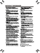
REA� ON -|- � ly. IN an ------ �� RT ET SET RET TROUBLE SHOOTING Refer to the following table if you are experiencing trouble with your camera. Contact an authorized technician if the table does not provide you with a solution to the trouble. Nothing appears on the screen. Check that the power cord and line connection between the camera and monitor are connected properly. Check that you have properly connected VIDEO cable to the camera VIDEO output jack. The image on the screen is dim.
Ultra Resolution Day & Night Dome Camera P/N 01.BSM.11.0070201C V3.