lP Video Router & TLR-DVR Controller Models: D4202 Installation / User Manual Digimerge Technologies Inc.
CAUTION RISK OF ELECTRIC SHOCK. DO NOT OPEN. ! CAUTION: TO REDUCE THE RISK OF ELECTRIC SHOCK, DO NOT REMOVE COVER (OR BACK). NO USER-SERVICEABLE PARTS INSIDE. REFER SERVICING TO QUALIFIED SERVICE PERSONNEL.
CONTENTS: GENERAL PRECAUTIONS--------------------------------------------------------------------------------------INTRODUCTION & FEATURES --------------------------------------------------------------------------------PACKAGE CONTENTS ------------------------------------------------------------------------------------------- 1 2 3 Getting Started IP ADDRESS --------------------------------------------------------------------------------------------------------REAR PANEL ----------------------------------
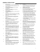
GENERAL PRECAUTIONS: 1. 2. 3. 4. 5. 6. 7. 8. 9. 10. 11. 12. 13. 14. Read Instructions All of the safety and operating instructions should be read and understood before the product is used. Retain Instructions The safety and operating instructions should be retained for future reference. Heed Warnings All warnings on the product and the instruction manual should be followed.
INTRODUCTION & FEATURES: Introduction Thank you for purchasing the IP Video Router and TLR-DVR Controller. This is an internet based digital video server capable of connecting up to 2 channels of video sources. The Video Web Server turns a standalone recorder into an IP -enabled, networkable recorder. It broadcasts compressed live video on-line (Intranet/Internet) via an Ethernet connection. It also enables DVR series products and cameras to connect to the internet for remote monitoring or remote control.
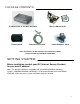
PACKAGE CONTENTS: IP Video Router & TLR-DVR Controller Terminal block Crossover LAN cable Owner’s Manual & CD Power Adapter & Cord CHECK YOUR PACKAGE TO MAKE SURE THAT YOU RECEIVED THE COMPLETE SYSTEM, INCLUDING THE COMPONENTS SHOWN ABOVE. GETTING STARTED: Before installation, contact your ISP (Internet Service Provider) for your own IP address. Note : The bundled software is compatible with the following Windows operating systems : WIN2000, WIN2003 and WINXP.
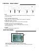
CONTROL - REAR PANEL: 1 2 3 4 5 1. LAN Connect the RJ45 standard pass through cable to the internet, or directly to a PC using the crossover cable 2. ACT & LINK LED’s (Actual & Link) When these LED’s are blinking it indicates that the network is in operation 3. VIDEO INPUT (BNC, 2 channels) Connect to a video source, such as a camera or DVR video output. 4. ALARM I/O (optional for advanced applications) Connect control devices, such as a DVR, Motion Sensors, external alarm signal inputs, etc 5.
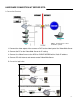
HARDWARE CONNECTION AT SERVER SITE: A . Connection Structure NOTE: The RS-485 to control the DVR is optional. 1. Connect the video output of the camera or DVR to the video input of the Video Web Server. 2. Connect the PC to the Video Web Server for IP setting. 3. Connect the Video Server to the ADSL or CABLE MODEM with a Static IP address. 4. Connect PC with Internet and remote control Video Web Server. B .
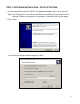
STEP 1: SOFTWARE INSTALLATION – STATIC IP SETTING: 1. Put the attached CD into the CD-ROM. The application program will install on your PC. Note: The CD contains a self-running installation that automatically starts when the CD is inserted. Follow the instructions for installation as indicated in the next few pages. 2. Press “Next”. 3. Choose the destination location and press “Next”.
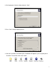
4. Set the program shortcut setting and press “Next”. 5. Press “Next” to begin copying the files 6. After the installation, the following files listed below will appear in your assigned path or file folder. There will be 6 files and 1 folder.
STEP 2: IP SETTING 1. Using the Crossover LAN cable connect the Video Web Server to the PC. Note : In some operating environments, users might need the standard CAT5 cable. RJ-45 POWER 2. Network setting for the PC. (The instruction is based on Win XP O/S. If your Operating System is Win 2000 or Win 2003, the setup procedure is similar to that of Win XP O/S.) Click twice 3.
4. Click on “INTERNET PROTOCOL (TCP/IP)” and then select “Properties” to setup 5. Click on “Use the following IP address” and set the IP address and subnet mask NOTE : 1. Before changing the PC network setting, please write down the original network setting in order to recover the original setting after the setup. (for static IP users) 2. The IP address should be 192.168.1.XXX. The setting of “XXX” could be set from 1 to 254 Do not use 10 since 192.168.1.10 is the default IP ); the subnet mask is 255.255.
3. When you see the control bar, this means that you have successfully logged into the program on the Video Web Server. Click on “System Config” to set up.(NOTE: If you don’t connect a camera or DVR to the Video Web Server, the only thing you will see is the control bar.) SYSTEM CONFIG 4. In the Peripheral setting, set the baud rate, ID and model that you want to remotely control later. Press the “APPLY” to enable the change after the setting. 5. Click on “System Config” again.
6. Disconnect the PC and Video Web Server, and link the static IP to the RJ -45 video web server. Static IP STEP 4: DVR REMOTE SETTING 1. Connect the DVR and monitor. 2. In the “Remote” setting, set the baud rate and ID the same as the “Peripheral” setting in the Video Web Server. Set the remote mode to RS-485 (see example below). A. 1 / 4 CH DVR (MENU) TIMER CAMERA RECORD ALARM DWELL REMOTE SYSTEM EVENT (REMOTE) REMOTE MODE : RS-485 BAUD RATE : 2400 ID : 001 B.
STEP 5: PIN CONFIGURATIONS After the remote setting, connect the DVR, noting the following pins. Video Web Server PIN 1, 6. RS485-A, RS485-B Use RS485-A & RS485-B serial communication signals to control digital units such as a DVR. PIN 4, 7, 8, 9. ALARM INPUT Use PIN 4,7,8,9 to receive the alarm input and then trigger the Video Server to send Email to users for the auto e-mail warning system. (Alarm 1, 2 are for CH1; alarm 3, 4 are for CH2) PIN 5. GND Ground PIN 2, 3.
STEP 6: CONNECTING TO A PC VIA THE INTERNET 1. Change the PC network setting to the original setting and link the PC to the internet. 2. Click twice to enter your User name & Password (Note : The default User Name and Password are both “admin”), and the static IP, which you have set for the Video Web Server in step 4.5. Then click OK to connect.
WHAT IS A DYNAMIC IP ADDRESS ? A Dynamic IP Address is a n IP (Internet Protocol) address that changes each time you connect to the internet. This cuts down on the number of IP addresses large consumer providers need because not all of their customers are using the service at any given time. It also cuts down on bandwidth usage by preventing consumers from hosting servers. Note: a number of companies have started to offer services aimed at updating DNS for dynamically connected clients.
2. Click on “Create Account” 3. Register your information (Username, E-mail address & password). Click on “Create Account” when the necessary information is completed 4. After registering your account, you will receive an e-mail, which contains instructions to activate your account. If you do not follow these directions within 48 hours, you will need to re-register your account. 5. Login your account.
6. Click on“Account” and “Add Host” 7. Users can set up their own DDNS HOST. For example, the user’s Host name is “avtech.dyndns .org”. Click on “Add Host” to finish the setting. (NOTE : Some routers don’t support some DDNS HOSTs) digimerge STEP 4: CONNECTING THE PC TO A ROUTER / ROUTER LOGIN: NOTE : The following settings are different from router to route r. Please read the instructions on your router thoroughly. 1.
2. Network setting for PC. (The instruction is based on Win XP O/S . If your O/S is Win 2000 or Win 2003, the setup procedure is similar to that of Win XP O/S.) Click twice 3.
4. Click on “INTERNET PROTOCOL (TCP/IP)” and then select “Properties” to setup 5. Choose “Obtain an IP address automatically” 6.
7. In the setting window, enter “ ipconfig” , and write down the router’s gateway(e.g. 192.168.1.1) 8. Close the window above. Enter the IP address ( router’s gateway: 192.168.1.1 ) to log in to the router from the Internet Explorer. Enter the login web page and key in the router’s user name and password. STEP 5: ROUTER SETTING (Please refer to your Router manual for the configuration) NOTE : In the router setting, there are four steps to follow. 1. Dial setting 2. DHCP setting 3.
1. Click on “INTERNET PORT” and choose your WAN type (e.g. PPPoE). Enter your “User Name” and “Password” to dial up the dynamic IP address. Press save after you set up. digimerge 2. Press “LOCAL PORT” and set “Start IP address” and “Number of IP address”. (For example, if the IP address of your Video Web Server is 192.168.1.10, then 10 is excluded from the setting range) Press save after you finish setting up. 3. In the “ADVANCED SETUP / Virtual Server”.
4. In the “ADVANCED SETUP / Dynamic DNS”, key in the “DNS Account”, “User Name” and “Password” that you applied in step 3. Press save after you set up. digimerge STEP 6 : IP SETTING 1. Connect the PC or Notebook to the Video Web Server using the crossover LAN cable. Note: In some operating environments, users might need the standard CAT5 cable. RJ-45 POWER (MENU) TIMER CAMERA RECORD ALARM DWELL PIP MOTION DISPLAY NETWORK USER SYSTEM EVENT PTZ In the DVR Menu, select “Network” (NETWORK) IP ADDRESS 061.
2. Network setting for PC. (The instruction is based on Win XP O/S . If your O/S is Win 2000 or Win 2003, the setup procedure is similar to that on Win XP O/S.) Click twice STEP 7: VIDEO WEB SERVER SETTING 1. To configure the Server IP, please click twice to enter the setup. 2. Key in the User Name, Password, and IP address (The default setting for the User Name and Password are both “admin”; IP address is 192.168.1.10, Port : 80). Click OK to connect.
3. When you see the control bar, you have successfully logged into the program on the Video Web Server. Click on “System Config” to set up. SYSTEM CONFIG 4. In the Peripheral setting, set baud rate, ID and the model that want to remotely control later. Press “APPLY” to enable the change after the setting. 5. Click on “System Config” again. In the Network setting, set the gateway the same as the router’s gateway(192.168.1.1). Press “APPLY” to enable the change after the setting.
STEP 8: DVR REMOTE SETTING 1. Connect the DVR and monitor. 2. In the “Remote” setting, set the baud rate and ID the same as the “Peripheral” setting on the video web server. Set the remote mode to RS-485.(see example below) A. 1 / 4 CH DVR (MENU) TIMER CAMERA RECORD ALARM DWELL REMOTE SYSTEM EVENT B.
PIN 5. GND Ground PIN 2, 3. NORMAL HIGH, NORMAL LOW Use PIN 2 or 3 to trigger an external device Please see the picture below for a 1CH DVR connected to the Video Web Server.(See Appendix #1) RS485-A Video Web Server Pin 1 1 CH DVR Pin 10 Pin 11 Pin 6 RS485-B STEP 10: CONNECTING ALL DEVICES ADSL modem (WAN end) DVR STEP 11: CONNECTING TO A PC VIA THE INTERNET 1. Change PC network setting to the original setting and link PC to the internet. 2.
SOFTWARE OPERATION AT THE REMOTE SITE Follow the steps below to connect to a remote site. (e.g. If you set up the server at your office with one static ADSL, you can remotely watch the video anywhere, with a networkable computer.) Step 1: Click twice to enter the Login setup (please refer to “software installation”) Step 2: Key in “User Name” and “ Password”. (e.g. “User Name” and “Password” is “dan”, and the IP address is 61.222.50.174). Click “OK” to establish the connection. NOTE: 1.
CONTROL PANEL AND BASIC OPERATION A. Video Web Server control panel 1 2 3 4 5 6 7 8 9 10 11 B. Digital device control panel 12 13 1 2 3 4 5 6 1. Camera video inputs 2. Quad screen, 7-9-10-13-16 screen 3. Zoom, PIP, Select, Lock, Search, Enter 4. Stop, Record, Rewind, Fast Forward, Pause, Slow, Play 5. Menu(Exit), Left, Right, Up, Down 14 1. Image transmission rate per second 6. Click on the arrow key to go to the “Video Web Server Control Panel” 2. Video Channels 3. Data transmission rate 4.
PLAYBACK OPERATION You will find the recorded file on the PC. Click twice to playback. 1 2 3 4 5 6 7 8 9 10 11 12 1. On Screen Display 2. Snapshot 3. Stop 4. Pause 5. Slow (1/2, 1/4, 1/8) 6. PLAY 7. Fast 8. OSD show / hide 9. System setting (Path of snapshot, text color, progress color, channel color) 10. Back Video 11. Next Video 12.
ADVANCED SETTINGS Click on “System Config” for advanced setting . SYSTEM CONFIG NETWORK NOTE : Apply-After all setting changes, press “apply” to refresh the data in the Video Web Server. Reboot-Press this button to restart the Video Web Server. To set up the network setting of the Video Web Server, check with your network administrator or Internet Service Provider. 1. You can get all the information, Server IP, Gateway, Net Mask & DNS, from your ISP company. 2.
FTP When the alarm is triggered, the video server will capture the instant picture and upload the captured image to the assigned FTP site. 1. You can get all the data from your MIS department. 2. The default uploading port is No.21. 3. You can set the uploading directory by yourself. ACCOUNT Set up the user’s account, password (Max 5 accounts) and authority. 1. User’s level: SUPERVISOR - controls all the functions USER LEVEL - control advanced functions GUEST LEVEL - control basic functions only 2.
FILE PATH You can modify the storing path for the recording file and snapshot images . TOOLBOX Upgrade the firmware. NOTE : Do not reboot the Video Web Server while it is upgrading the firmware. 1. Firmware Version : For the current firmware version, you can click on the “Find” button to get the latest firmware from your PC. Press “Upgrade Firmware” to upgrade it. 2.Turbo step: You can set the turbo step when the turbo function is open. ALARM Set up the ALARM function.
ONLINE USER Get online user’s information 1. Info refresh : Refresh the online users’ information FAQ’S 1. With regards to direct connection to a PC, could I connect the video server with remote PC without connecting it to the Internet ? ANS: Yes, you can connect the Video server with remote PC using the Crossover cable directly. 2. If I do not have any network in my office or house, could I use this system? ANS: Yes, you could use this unit.
SPECIFICATIONS Video Input 2 channels for analog and digital products, 1.
APPENDIX #1 – DVR CONTROL PIN CONFIGURATIONS FOR CONNECTION TO A 1CH DVR DVR Web Server RS232-TX GND RS232-RX RS485-B VIDEO LOSS RS485-A SWITCH OUT DISK FULL ERROR OUT ALARM RESET REC STAR ALARM INPUT EXTERNAL ALARM NC EXTERNAL ALARM COM EXTERNAL ALARM NO GND ALARM INPUT2 ALARM INPUT1 ALARM INPUT3 NORMAL LOW ALARM INPUT4 NORMAL HIGH RS485-B RS485-A PIN CONFIGURATIONS FOR CONNECTION TO 4CH, 9CH & 16CH DMR DMR EXTERNAL ALARM NO EXTERNAL ALARM COM RS485-A RS485-B RS232-TX RS232-RX ALARM INPUT 1 ALARM INPUT
2) Set the “Remote” function on the DVR. NOTE : Remote mode : RS-485, Baud rate : selectable, ID : same as “Peripheral Control” in the Video Web Server. A. 1 / 4 CH DVR (MENU) TIMER CAMERA RECORD ALARM DWELL REMOTE SYSTEM EVENT (REMOTE) REMOTE MODE:RS-485 BAUD RATE:selectable ID:020 B. 4 / 9 / 16 CH DMR (MENU) SEARCH TIMER RECORD CAMERA SYSTEM EVENT (SYSTEM) : : REMOTE MODE:RS-485 BAUD RATE:selectable REMOTE ID:021 3) Set the “Peripheral Control” in the system configuration of the Video Web Server.
APPENDIX #2 – SENDING E-MAIL 1) Connect the Sub-D plug on the Video Web Server with the COM/NO ports of the Sensor. Video Web Server Pin 5 GND N.O. Sensor ALARM INPUT Pin 4,7, 8 or 9 A normally open contact/sensor can be connected where Pin 5 is Ground and Pin 4, 7, 8 and 9 is the Alarm Input 2) Set the “Mail setting ” item in the system configure. digimerge.eng digimerge.eng dliu@digimerge.
APPENDIX #3 – SOFTWARE DOWNLOAD Step 1 : Please connect the PC to the Internet and key in the Video Web Server’s IP address (ex : 61.222.50.160) in the browser. Then press E NTER. Step 2 : Click on “Download Windows AP” to download the application program and save “Setup.exe” in the HDD. Step 3 : Click on “Setup.exe” twice to install the application program. Step 4 Click on twice to enter the Login setup and refer to “software installation” for other operations.
REFEFENCE NOTES : Static IP 1. In step 2.5 : Please make sure that your IP address is 192.168.1.XXX. The setting of “XXX” could be set from 1 to 254, where 10 is excluded (The default IP is 192.168.1.10 ) 2. In step 4.4 : Please make sure that the Peripheral setting is the same as the setting on the DVR, which you want to remotely control later. 3. In step 6.2 : The Server IP is the IP you set in step 4.5. Dynamic IP 1. In step 3.7 : Some routers don’t support the DDNS HOST. 2. In step 4.
LIMITED WARRANTY Warranty : Subject to the exclusions and limitations below, Digimerge warrants to the initial end-user purchaser that the product will be free from defects in material and workmanship for a period of one year from the date of purchase. For valid warranty claims made during the warranty period, upon proof of purchase, defective products will, at the election of Digimerge, be repaired or replaced without charge.
CARE AND MAINTENANCE: Please follow these instructions to ensure proper care and maintenance of this system Keep your monitor and camera dry. If it gets wet, wipe it dry immediately. Use and store your unit in normal temperature environment. Extreme temperatures can shorten the life of the electronic devices. Handle the monitor carefully. Dropping it can cause serious damage to the unit. Occasionally clean the unit with a damp cloth to keep it looking new.
Digimerge Technologies Inc. 300 Alden Road Markham Ontario L3R 4C1 www.digimerge.