
Data Sheet


2/10/2018 Zybo Z7 Reference Manual [Reference.Digilentinc]
https://reference.digilentinc.com/reference/programmable-logic/zybo-z7/reference-manual 31/33
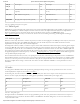
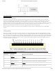
Table 16.1. Zybo Z7 Pmod Pinout
The standard Pmod ports are connected to the Zynq PL via 200 Ohm series resistors. The series resistors prevent short circuits that can
occur if the user accidentally drives a signal that is supposed to be used as an input. The downside to this added protection is that these
resistors can limit the maximum switching speed of the data signals. If the Pmod being used does not require high-speed access, then the
standard Pmod port should be used to help prevent damage to the devices.
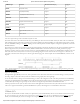
The MIO Pmod port is connected to the MIO bus in the Zynq PS via 200 Ohm series resistors. Like the standard Pmod port, these series
resistors add protection at the cost of maximum switching speed. Since these data signals are connected to the MIO interface, they can only
be accessed by the PS peripheral controller cores. The GPIO (), UART, I2C, and SPI cores can all be used to drive devices connected to this
Pmod. Note that the pin layout of the UART and I2C cores will not align perfectly with the typical Pmod pinouts for these interfaces. This
means that UART or I2C devices connected to this Pmod may require some of the pins to be swapped around externally using individual
wires between the Zybo Z7 and the Pmod.
The Pmod port labeled “XADC” is wired to the auxiliary analog input pins of the PL. Depending on the Zynq PL configuration, this port
can be used to input differential analog signals to the analog-to-digital converter inside the Zynq XADC core. Any or all pairs in the port can
be configured either as analog input or digital input-output.
In analog input mode, the voltage on these pins must be limited to 1V peak-to-peak. In digital mode, the regular VCCO-dependent limits
apply. See Xilinx datasheets for more information.
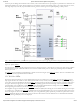
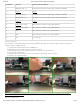
The Dual Analog/Digital Pmod on the Zybo Z7 differs from the rest in the routing of its traces. The eight data signals are grouped into
four pairs, with the pairs routed closely coupled for better analog noise immunity. Pins 1 and 7, pins 2 and 8, pins 3 and 9, and pins 4 and 10
are paired up. Furthermore, each pair has a partially loaded anti-alias filter laid out on the PCB. The filter does not have capacitors C101-
C104 loaded. In designs where such filters are desired, the capacitors can be manually loaded by the user.
NOTE: The coupled routing and the anti-alias filters might limit the data speeds when used for digital signals.
The XADC core within the Zynq is a dual channel 12-bit analog-to-digital converter capable of operating at 1 MSPS. Either channel can be
driven by any of the auxiliary analog input pairs connected to the XADC port. The XADC core is controlled and accessed from the PL via
the Dynamic Reconfiguration Port (DRP). The DRP also provides access to voltage monitors that are present on each of the Zynq's power
rails, and a temperature sensor that is internal to the Zynq. For more information on using the XADC core, refer to the Xilinx document
titled “7 Series FPGAs and Zynq-7000 All Programmable SoC XADC Dual 12-Bit 1 MSPS Analog-to-Digital Converter.” It is also possible
to access the XADC core directly using the PS, via the “PS-XADC” interface. This interface is described in full in chapter 30 of the Zynq
Technical Reference Manual.
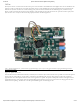
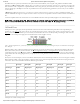
The High-speed Pmod ports use the standard Pmod connector, but have their data signals routed as impedance matched differential pairs
for maximum switching speeds. They have pads for loading resistors for added protection, but the Zybo Z7 ships with these loaded as 0-
Ohm shunts. With the series resistors shunted, these Pmods offer no protection against short circuits, but allow for much faster switching
speeds. The signals are paired to the adjacent signals in the same row: pins 1 and 2, pins 3 and 4, pins 7 and 8, and pins 9 and 10.
Traces are routed 80 ohm (+/- 10%) differential.
These ports should be used only when high speed signaling is required or the other suitable ports are occupied. If used as single-ended,
coupled pairs may have significant cross-talk. In applications where this is a concern, the standard Pmod port should be used. Another
option would be to ground one of the signals and use its pair for the signal-ended signal.
Since the High-Speed Pmods have 0-ohm shunts instead of protection resistors, the operator must take precaution to ensure that they do
not cause any shorts.
rm (https://reference.digilentinc.com/tag/rm?do=showtag&tag=rm), doc (https://reference.digilentinc.com/tag/doc?do=showtag&tag=doc), zybo-z7
(https://reference.digilentinc.com/tag/zybo-z7?do=showtag&tag=zybo-z7)
16.1 Standard Pmod
16.2 MIO Pmod
16.3 Dual Analog/Digital Pmod (XADC Pmod)
16.4 High-Speed Pmod
First Name
Last Name
Email Address
Subscribe to our Newsletter