
Data Sheet

2/10/2018 Zybo Z7 Reference Manual [Reference.Digilentinc]
https://reference.digilentinc.com/reference/programmable-logic/zybo-z7/reference-manual 29/33
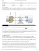
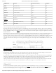
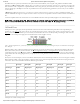
Pin Number Function Zybo Z7 Connection Details
6 MIPI CSI-2 Lane 1 (+) Terminated and connected to 2 FPGA pins as described in XAPP894
7 GND () GND ()
8 MIPI CSI-2 Clock (-) Terminated and connected to 2 FPGA pins as described in XAPP894
9 MIPI CSI-2 Clock (+) Terminated and connected to 2 FPGA pins as described in XAPP894
10 GND () GND ()
11 GPIO ()/Power enable Direct Connection to FPGA, usage module-dependent
12 GPIO ()/Clock feedback Direct Connection to FPGA, usage module-dependent
13 SCL Direct Connection to FPGA, with 1.5 KOhm Pull-up
14 SDA Direct Connection to FPGA, with 1.5 KOhm Pull-up
15 3V3 3.3 V Power rail
Table 15.1. Pcam Pin-out
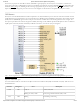
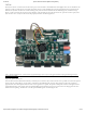
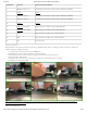
Pcam modules are connected to the Pcam host port using a flexible flat cable (FFC). To connect the cable to the Zybo Z7 follow these
instruction (Figure 15.2 depicts each step):
1. Locate the Pcam connector between the two HDMI ports.
2. Pull directly up on the off-white colored tab to open the connector.
3. Insert the FFC with the contacts facing the top edge, away from the center of the Zybo Z7.
4. Ensure the FFC is fully inserted.
5. Gently press down on both sides of the off-white colored tab to latch the FFC into the connector.
6. The FFC is now connected properly.
(https://reference.digilentinc.com/_detail/reference/programmable-logic/zybo-z7/zybo-z7-pcam-attach.png?id=reference%3Aprogrammable-
logic%3Azybo-z7%3Areference-manual)
Figure 15.2. Attaching a Pcam