
Data Sheet

2/10/2018 Zybo Z7 Reference Manual [Reference.Digilentinc]
https://reference.digilentinc.com/reference/programmable-logic/zybo-z7/reference-manual 28/33
(https://reference.digilentinc.com/_detail/reference/programmable-logic/zybo-z7/fan_fig.png?id=reference%3Aprogrammable-logic%3Azybo-
z7%3Areference-manual)
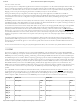
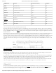
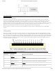
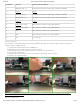
Figure 14.2. Fan Speed Feedback Signal
It is possible to monitor the temperature of the Zynq device during operation over JTAG from the hardware server in Vivado. The
maximum recommended operating temperature for the Zynq-7020 device is 85°C. If your design causes the temperature of the Zynq to
approach the maximum, Digilent recommends you turn off the Zybo Z7-20 and attach a fan before running your design again. The
temperature that the Zynq reaches is largely based on the number of resources used in the Zynq PL and the rate at which they are switching.
Most designs should not reach temperatures that will require a fan. When powering the Zybo Z7-20 from USB, a fan is not necessary
because the current limit will cause the board to reset before a dangerous amount of heat can be generated.
The fan connector is not loaded on the Zybo Z7-10 because additional cooling is typically not needed with the fewer available FPGA
resources.
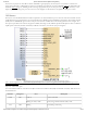
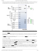
The Pcam port included on the Zybo Z7 is a 15-pin, 1 mm pitch, zero insertion force (ZIF) connector designed specifically for attaching
camera sensor modules to host systems. The Pcam connector pin-out is rigidly defined and includes a two lane MIPI CSI-2 bus for camera
data, an I2C bus for camera configuration, two additional general purpose signals, and 3.3 V for powering the camera module, as depicted in
Figure 15.1 and Table 15.1. Digilent is developing a catalog of Pcam peripheral camera modules with various different types of sensors that
all conform to this pin-out. The pin-out was also chosen so that many camera modules designed to work with the Raspberry Pi will also
work when connected to the Pcam port.
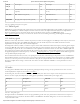
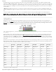
(https://reference.digilentinc.com/_detail/reference/programmable-logic/zybo-z7/zybo-z7-pcam-pins.png?id=reference%3Aprogrammable-
logic%3Azybo-z7%3Areference-manual) Figure 15.1. Pcam Pin-out
Pin Number Function Zybo Z7 Connection Details
1 GND () GND ()
2 MIPI CSI-2 Lane 0 (-) Terminated and connected to 2 FPGA pins as described in XAPP894
3 MIPI CSI-2 Lane 0 (+) Terminated and connected to 2 FPGA pins as described in XAPP894
4 GND () GND ()
5 MIPI CSI-2 Lane 1 (-) Terminated and connected to 2 FPGA pins as described in XAPP894
15 Pcam Port