
Data Sheet

2/10/2018 Zybo Z7 Reference Manual [Reference.Digilentinc]
https://reference.digilentinc.com/reference/programmable-logic/zybo-z7/reference-manual 27/33
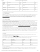
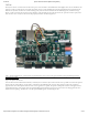
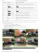
The Zybo Z7-20 has a connector that can be used to power a fan mounted to the included heat sink. Digilent sells a 5V fan suitable for this
purpose. In order to attach the fan to the Zybo Z7-20 heat sink, two of the included screws must be tightened into the space between the
heat sink fins (the heat sink does not contain mounting holes). The fan must be attached with the label facing down, towards the Zynq
device, in order to push the air flow in the correct direction. After mounting the fan, plug the fan into the 3-pin fan connector (J14) on the
Zybo Z7-20 to use it. A Zybo Z7-20 with the fan properly attached is shown in Figure 14.1.
(https://reference.digilentinc.com/_detail/reference/programmable-logic/zybo-z7/zybo-z7-fan.png?id=reference%3Aprogrammable-logic%3Azybo-
z7%3Areference-manual)
Figure 14.1. Zybo Z7-20 with Fan
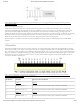
Once the fan has been installed and connected, it will always be on when the Zybo Z7-20 is turned on. It is possible to monitor the speed of
the fan using the “FAN_FB_PU” signal, which is connected to the feedback signal of the fan. This generates a pulse with a frequency
proportional to the rotation speed of the fan. Each rotation generates two pulses. The period of these pulses shortens with higher rotation
speed and lengthens at slower speeds. If the fan speed feedback signal is held at logic high or logic low and is not changing then the fan is
locked and is not spinning. The behavior of the fan speed feedback signal is shown in Figure 14.2.
14 Fan