
Data Sheet

2/10/2018 Zybo Z7 Reference Manual [Reference.Digilentinc]
https://reference.digilentinc.com/reference/programmable-logic/zybo-z7/reference-manual 26/33
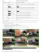
resistors to prevent damage from inadvertent short circuits (a short circuit could occur if a pin assigned to a push-button or slide switch was
inadvertently defined as an output). The push-buttons are “momentary” switches that normally generate a low output when they are at rest,
and a high output only when they are pressed. Slide switches generate constant high or low inputs depending on their position.
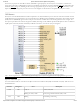
(https://reference.digilentinc.com/_detail/reference/programmable-logic/zybo-z7/zybo-z7-gpio.png?id=reference%3Aprogrammable-logic%3Azybo-
z7%3Areference-manual)
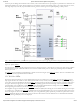
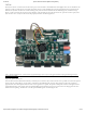
Figure 13.1. Zybo Z7 GPIO ()
The high-efficiency LEDs are anode-connected to the Zynq via 330-ohm resistors, so they will turn on when a logic high voltage is applied
to their respective I/O pin. Additional LEDs that are not user-accessible indicate power-on, FPGA programming status, and USB and
Ethernet port status.
The LED () and two pushbuttons attached directly to the PS are accessed using the Zynq GPIO () controller. This core is described in full
in Chapter 14 of the Zynq Technical Reference Manual.
The Zybo Z7-20 board contains two tri-color LEDs and the Zybo Z7-10 contains one tri-color LED (). Each tri-color LED () has three
input signals that drive the cathodes of three smaller internal LEDs: one red, one blue, and one green. Driving the signal corresponding to
one of these colors high will illuminate the internal LED (). The input signals are driven by the Zynq PL through a transistor, which inverts
the signals. Therefore, to light up the tri-color LED (), the corresponding signals need to be driven high. The tri-color LED () will emit a
color dependent on the combination of internal LEDs that are currently being illuminated. For example, if the red and blue signals are
driven high and green is driven low, the tri-color LED () will emit a purple color.
Note: Digilent strongly recommends the use of pulse-width modulation (PWM) when driving the tri-color LEDs. Driving any of the inputs
to a steady logic ‘1’ will result in the LED () being illuminated at an uncomfortably bright level. You can avoid this by ensuring that none of
the tri-color signals are driven with more than a 50% duty cycle. Using PWM also greatly expands the potential color palette of the tri-color
LED (). Individually adjusting the duty cycle of each color between 50% and 0% causes the different colors to be illuminated at different
intensities, allowing virtually any color to be displayed.
13.1 Tri-Color LEDs