
Data Sheet

2/10/2018 Zybo Z7 Reference Manual [Reference.Digilentinc]
https://reference.digilentinc.com/reference/programmable-logic/zybo-z7/reference-manual 25/33
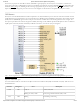
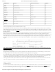
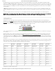
SSM2603 pin Protocol Direction from Zynq Zynq pin
BCLK I²S (Serial Clock) Output R19
PBDAT I²S (Playback Data) Output R18
PBLRC I²S (Playback Channel Clock) Output T19
RECDAT I²S (Record Data) Input R16
RECLRC I²S (Record Channel Clock) Output Y18
SDIN I²C (Data) Input/Output N17
SCLK () I²C (Clock) Output N18
MUTE Digital Enable (Active Low) Output P18
MCLK Master Clock Output R17
Table 12.2. Digital audio signal with the SSM2603 in default slave mode
The audio codec needs to be clocked from the Zynq on the MCLK pin. This master clock will be used by the audio codec to establish the
audio sampling frequency. This clock is required to be an integer multiple of the desired sampling rate. The default settings require a master
clock of 12.288 Mhz, resulting in a 48 kHz () sampling rate. For other frequencies and their respective configuration parameters, consult the
SSM2603 datasheet.
The codec has two modes: master and slave, with the slave being default. In this mode, the direction of the signals is specified in Table 12.2.
When configured as master, the direction of BCLK, PBLRC and RECLRC is inverted. In this mode, the codec generates the proper
frequencies for these clocks. No matter where the clocks are generated, PBDAT needs to be driven out and RECDAT sampled in sync with
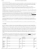
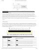
them. The master clock is always driven out of the Zynq. The timing diagram of an I²S stream can be seen on Figure 12.1. Note the one-
cycle delay of the data stream with respect to the left/right clock changing state. Audio samples are transmitted MSB first, noted as 1 in the
diagram.
(https://reference.digilentinc.com/_detail/reference/programmable-logic/zybo-z7/zybo-z7-audio.png?id=reference%3Aprogrammable-logic%3Azybo-
z7%3Areference-manual)
Figure 12.1. I²S timing diagram.
The digital mute signal (MUTE) is active-low, with a pull-down resistor. This means that when not used in the design, it will stay low and
the analog outputs of the codec will stay muted. To enable the analog outputs, drive this signal high.
To use the audio codec in a design with non-default settings, it needs to be configured over I2C. The audio path needs to be established by
configuring the (de)multiplexers and amplifiers in the codec. Some digital processing can also be done in the codec. Configuration is read
out and written by accessing the register map via I2C transfers. The register map is described in the SSM2603 datasheet.
A demo project that uses the Zybo Z7 audio codec in a bare-metal application can be found on the Zybo Z7 Resource Center. The audio
codec is also supported in Petalinux generated embedded Linux systems, and will appear as a standard ALSA audio device.
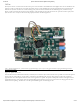
The Zybo Z7 board includes four slide switches, four push-buttons, four individual LEDs, and two tri-color LEDs connected to the Zynq
PL, as shown in Figure 13.1 (the Zybo Z7-10 only has one tri-color LED ()). There are also two pushbuttons and one LED () connected
directly to the PS via MIO pins, also shown in Figure 13.1. The push-buttons and slide switches are connected to the Zynq via series
13 Basic I/O