
Data Sheet

2/10/2018 Zybo Z7 Reference Manual [Reference.Digilentinc]
https://reference.digilentinc.com/reference/programmable-logic/zybo-z7/reference-manual 23/33
Table 10.1. Ethernet status LEDs
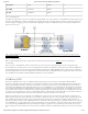
The Zynq incorporates two independent Gigabit Ethernet Controllers. They implement a 10/100/1000 half/full duplex Ethernet MAC. Of
these two, GEM 0 can be mapped to the MIO pins where the PHY interfaces. Since the MIO bank is powered from 1.8V, the RGMII
interface uses 1.8V HSTL Class 1 drivers. For this I/O standard an external reference of 0.9V is provided in bank 501 (PS_MIO_VREF).
Mapping out the correct pins and configuring the interface is handled by the Zybo Z7 Vivado board files.
Although the default power-up configuration of the PHY might be enough in most applications, the MDIO bus is available for
management. The RTL8211E-VL is assigned the 5-bit address 00001 on the MDIO bus. With simple register read and write commands,
status information can be read out or configuration changed. The Realtek PHY follows industry-standard register map for basic
configuration.
The RGMII specification calls for the receive (RXC) and transmit clock (TXC) to be delayed relative to the data signals (RXD[0:3], RXCTL
and TXD[0:3], TXCTL). Xilinx PCB guidelines also require this delay to be added. The RTL8211E-VL is capable of inserting a 2ns delay on
both the TXC and RXC so that board traces do not need to be made longer.
On an Ethernet network each node needs a unique MAC address. To this end, the one-time-programmable (OTP) region of the Quad-SPI
flash has been programmed at the factory with a 48-bit globally unique EUI-48/64™ compatible identifier. The OTP address range
[0x20;0x25] contains the identifier with the first byte in transmission byte order being at the lowest address. Refer to the Flash memory
datasheet (http://www.cypress.com/file/177966/download) for information on how to access the OTP regions. When using Petalinux, this is
automatically handled in the U-boot boot-loader, and the Linux system is automatically configured to use this unique MAC address. The
identifier is also printed on a sticker found on the top-side of the Zybo Z7 right next to the mode jumper (JP5) and above the headphone
output jack.
For getting started using the ethernet port in a bare-metal application, Xilinx provides a lwip TCP/IP stack that can be automatically
generated in Xilinx SDK along with an echo server example. When using the Zybo Z7 with a Petalinux generated embedded Linux system,
the ethernet port will automatically appear as a network device typically named eth0. See the Petalinux and Xilinx SDK documentation for
more information.
For more low-level information on using the Zynq-7000 Gigabit Ethernet MAC, refer to the Xilinx Zynq Technical Reference Manual.
The Zybo Z7 contains one unbuffered source port (output, labeled HDMI TX), and one buffered sink port (input, labeled HDMI RX).
Both ports use HDMI type-A receptacles with the data and clock signals terminated and connected to the Zynq PL. The buffer used on the
HDMI RX port works by terminating, equalizing, conditioning, and forwarding the HDMI stream between the connector and FPGA pins.
The HDMI TX port does not include a buffer for improving signal integrity, but does include an HDMI multiplexer configured as a simple
switch. This device is used to prevent displays from back-powering the Zybo Z7, and otherwise has no effect on functionality. The benefit
this adds is to make it possible to power cycle the Zybo Z7 while a display is attached to HDMI TX, which was not possible on the Zybo.
Both HDMI and DVI systems use the same TMDS signaling standard, directly supported by Zynq PL's user I/O infrastructure. Also,
HDMI sources are backward compatible with DVI sinks, and vice versa. Thus, simple passive adaptors (available at most electronics stores)
can be used to drive a DVI monitor or accept a DVI input. The HDMI receptacle only includes digital signals, so only DVI-D mode is
possible.
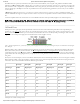
The 19-pin HDMI connectors include three differential data channels, one differential clock channel, five GND () connections, a one-wire
Consumer Electronics Control (CEC) bus, a two-wire Display Data Channel (DDC) bus that is essentially an I2C bus, a Hot Plug Detect
(HPD) signal, a 5V signal capable of delivering up to 50mA, and one reserved (RES) pin. All non-power signals are wired to the Zynq PL
with the exception of RES, and the CEC bus of the HDMI RX port on the Zybo Z7-10 (it is connected on the Zybo Z7-20).
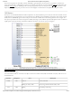
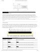
Pin/Signal HDMI TX HDMI RX
Description FPGA
pin
Description FPGA
pin
D[2]_P,
D[2]_N
Data output B19,
A20
Data input N20, P20
D[1]_P,
D[1]_N
Data output C20, B20 Data input T20, U20
D[0]_P,
D[0]_N
Data output D19,
D20
Data input V20,
W20
11 HDMI