
Data Sheet

2/10/2018 Zybo Z7 Reference Manual [Reference.Digilentinc]
https://reference.digilentinc.com/reference/programmable-logic/zybo-z7/reference-manual 22/33
Note that if your project uses the USB host feature (embedded or general purpose), then the Zybo Z7 is very likely to consume more
current than is allowed by a USB peripheral, causing it to periodically reset. When this occurs the PGOOD LED () will quickly flicker and
the DONE LED () will go low, indicating the PL is no longer programmed. To prevent this, power the Zybo Z7 by a 5V battery or wall
adapter capable of providing more power. See section “1 Power Supplies” for information on acceptable non-USB power sources.
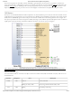
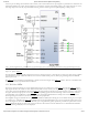
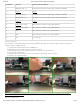
The Zybo Z7 uses a Realtek RTL8211E-VL PHY to implement a 10/100/1000 Ethernet port for network connection. The PHY connects
to MIO Bank 501 (1.8V) and interfaces to the Zynq-7000 AP SoC via RGMII for data and MDIO for management. The auxiliary interrupt
(INTB) and reset (PHYRSTB) signals connect to PL pins to be accessed via EMIO. The connection diagram can be seen on Figure 10.1.
After power-up the PHY starts with Auto Negotiation enabled, advertising 10/100/1000 link speeds and full duplex. If there is an Ethernet-
capable partner connected, the PHY automatically establishes a link with it, even with the Zynq not configured.
(https://reference.digilentinc.com/_detail/reference/programmable-logic/zybo-z7/zybo-z7-eth.png?id=reference%3Aprogrammable-logic%3Azybo-
z7%3Areference-manual)
Figure 10.1. Ethernet PHY signals
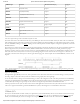
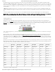
Two status indicator LEDs are on-board near the RJ-45 connector that indicate traffic (LD8) and valid link state (LD7). Table 10.1 shows
the default behavior.
Function Designator State Description
LINK LD7 Steady on Link 10/100/1000
Blinking 0.4s ON, 2s OFF Link, Energy Efficient Ethernet (EEE) mode
ACT LD8 Blinking Transmitting or Receiving
10 Ethernet