
Data Sheet

2/10/2018 Zybo Z7 Reference Manual [Reference.Digilentinc]
https://reference.digilentinc.com/reference/programmable-logic/zybo-z7/reference-manual 21/33
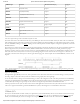
SD_CCLK Clock MIO40 5
SD_CMD Command MIO41 3
SD_CD Card Detect MIO47 9
Table 8.1. MicroSD pinout
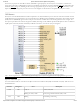
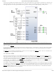
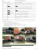
The SD slot is powered from 3.3V, but is connected through MIO Bank 1/501 (1.8V). Therefore, a TI TXS02612 level shifter performs this
translation. The TXS02612 is actually a 2-port SDIO port expander, but only its level shifter function is used. The connection diagram can
be seen on Figure 8.1. Mapping out the correct pins and configuring the interface is handled by the Zybo Z7 board files, available on the
Zybo Z7 resource center.
(https://reference.digilentinc.com/_detail/reference/programmable-logic/zybo-z7/zybo-z7-sd.png?id=reference%3Aprogrammable-logic%3Azybo-
z7%3Areference-manual)
Figure 8.1. microSD slot signals
Both low speed and high speed cards are supported, the maximum clock frequency being 50 MHz (). A Class 4 card or better is
recommended.
Refer to section “2.1 microSD Boot Mode” for information on how to boot from a microSD card that contains a Zynq Boot Image.
The microSD is also commonly used to store non-configuration data needed by the application. If doing this from a bare-metal application,
the microSD card can be freely accessed using standalone libraries included with a Xilinx SDK BSP project. If doing this from a Petalinux
generated embedded Linux system, the microSD can be mounted/accessed like a standard block device, typically with a device node named
/dev/mmcblk0. See the Petalinux and Xilinx SDK documentation for more information.
The Zybo Z7 implements one of the two available PS USB OTG interfaces on the Zynq device. A Microchip USB3320 USB 2.0
Transceiver Chip with an 8-bit ULPI interface is used as the PHY. The PHY features a complete HS-USB Physical Front-End supporting
speeds of up to 480Mbs. The PHY is connected to MIO Bank 1/501, which is powered at 1.8V. The usb0 peripheral is used on the PS,
connected through MIO[28-39]. The USB OTG interface can act as an embedded host or a peripheral device. The USB mode is controlled
from software by manipulating the USB0 peripheral controller in the Zynq PS. When acting as a peripheral, the USB Micro AB connector
(J10) should be used to connect to a USB host device, and JP1 and JP2 should not be shorted. When acting as an embedded host, the USB
A connector (J11) should be used to connect to a USB peripheral device, and JP2 should be shorted while JP1 is not shorted. The Zybo Z7
should never have a peripheral device and a host device connected to these two connectors at the same time.
While in host mode, the Zybo Z7 is technically an “embedded host”, because it does not provide the required 150 µF of capacitance on
VBUS required to qualify as a general purpose host. It is possible to modify the Zybo Z7 so that it complies with the general purpose USB
host requirements by loading C71 with a 150 µF capacitor and shorting JP1. Only those experienced at soldering small components on
PCBs should attempt this rework. Most USB peripheral devices will work just fine without loading C71. Whether the Zybo Z7 is configured
as an embedded host or a general purpose host, it can provide 500 mA on the 5V VBUS line. Note that loading C71 may cause the Zybo Z7
to reset when booting embedded Linux while powered from the USB port, regardless of if any USB device is connected to the host port.
This is caused by the in-rush current that C71 causes when the USB host controller is enabled and the VBUS power switch (IC12) is turned
on.
9 USB Host/OTG