
Data Sheet


2/10/2018 Zybo Z7 Reference Manual [Reference.Digilentinc]
https://reference.digilentinc.com/reference/programmable-logic/zybo-z7/reference-manual 20/33
The external system reset button, labeled PS-SRST, resets the Zynq device without disturbing the debug environment. For example, the
previous break points set by the user remain valid after system reset. Due to security concerns, system reset erases all memory content
within the PS, including the On-Chip-Memory (OCM). The PL is also cleared during a system reset. System reset does not cause the boot
mode strapping pins to be re-sampled. After changing boot moode jumpers a power cycle is needed to act on the new setting.
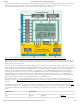
The Zybo Z7 includes an FTDI FT2232HQ USB-UART bridge (attached to connector J12) that lets you use PC applications to
communicate with the board using standard COM port commands (or the tty interface in Linux). Drivers are automatically installed in
Windows and newer versions of Linux when the Zybo Z7 is attached. Serial port data is exchanged with the Zynq using a two-wire serial
port (TXD/RXD). After the drivers are installed, I/O commands can be used from the PC directed to the COM port to produce serial data
traffic on the Zynq pins. The port is tied to PS (MIO) pins and can be used in combination with the UART 1 controller.
The Zynq presets file (available in the Zybo Z7 Resource Center (https://reference.digilentinc.com/reference/programmable-logic/zybo-z7/start))
takes care of mapping the correct MIO pins to the UART 1 controller and uses the following default protocol parameters: 115200 baud rate,
1 stop bit, no parity, 8-bit character length.
Two on-board status LEDs provide visual feedback on traffic flowing through the port: the transmit LED () (LD11) and the receive LED ()
(LD10). Signal names that imply direction are from the point-of-view of the DTE (Data Terminal Equipment), in this case the PC.
The FT2232HQ is also used as the controller for the Digilent USB-JTAG circuitry, but the USB-UART and USB-JTAG functions behave
entirely independent of one another. Programmers interested in using the UART functionality of the FT2232 within their design do not
need to worry about the JTAG circuitry interfering with the UART data transfers, and vice-versa. The combination of these two features
into a single device allows the Zybo Z7 to be programmed, communicated with via UART, and powered from a computer attached with a
single Micro USB cable.
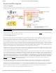
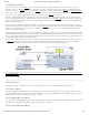
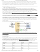
The connections between the FT2232HQ and the Zynq-7000 are shown in Figure 7.1.
(https://reference.digilentinc.com/_detail/reference/programmable-logic/zybo-z7/zybo-z7-uart.png?id=reference%3Aprogrammable-logic%3Azybo-
z7%3Areference-manual) Figure 7.1. UART Connections
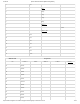
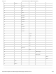
The Zybo Z7 provides a microSD slot (J4) for non-volatile external memory storage as well as booting the Zynq. The slot is wired to Bank
1/501 MIO[40-45], and also includes a card detect signal attached to MIO 47. On the PS side peripheral SDIO 0 is mapped out to these
pins and controls communication with the SD card. The pinout can be seen in Table 8.1. The peripheral controller supports 1-bit and 4-bit
SD transfer modes, but does not support SPI mode. Based on the Zynq Technical Reference Manual
(http://www.xilinx.com/support/documentation/user_guides/ug585-Zynq-7000-TRM.pdf), SDIO host mode is the only mode supported.
Signal Name Description Zynq Pin SD Slot Pin
SD_D0 Data[0] MIO42 7
SD_D1 Data[1] MIO43 8
SD_D2 Data[2] MIO44 1
SD_D3 Data[3] MIO45 2
7 USB-UART Bridge (Serial Port)
8 microSD Slot