
Data Sheet


2/10/2018 Zybo Z7 Reference Manual [Reference.Digilentinc]
https://reference.digilentinc.com/reference/programmable-logic/zybo-z7/reference-manual 15/33
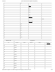
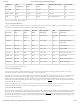
Connector
Type
JP6
Configuration
Connector
Label
Schematic net
name
Min/Rec/Max Voltage
(V)
Current Limit
(A)
Barrel jack WALL J17 VJACK 4.5/5/5.5 4.0
Battery/Other BAT JP6, J16 VU5V0 4.5/5/5.5 4.0
USB USB J12 VBUS See USB specification 0.75
Table 1.1.1. Zybo Z7 Power Input Specifications
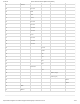
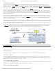
Table 1.2.1 describes the characteristics the Zybo Z7's on-board power rails. It can be used to estimate power consumption for a project, or
determine how much current attached peripherals can draw before being limited.
Net name
Upstream net
name
Power IC
Type
Power IC
Label
Min/Typ/Max
Voltage (V)
Max.
Current
Major Devices and
Connectors
VCC5V0 VU5V0 Power
protection
IC26 2.3V/5V/5.7V See Table
1.1.1
Power input
VCC3V3 VCC5V0 Buck IC25 3.3V +-10% 1.5A FPGA banks, Ethernet,
USB, HDMI
VCC1V0 VCC5V0 Buck IC25 1.0V +-5% 2.1A FPGA, Ethernet
VCC1V35 VCC5V0 Buck IC25 1.35V +-5% 1.2A FPGA, DDR3
VCC1V8 VCC5V0 Buck IC25 1.8V +-10% 0.6A FPGA, Ethernet, USB
XADC_1V8 VCC5V0 LDO IC25 1.8V +-10% 0.1A FPGA XADC
XADC_1V25 VCC3V3 LDO IC27 1.25V +-0.12% 5mA FPGA XADC reference
ANA3V3 VCC5V0 LDO IC5 3.3V +-10% 0.1A Analog audio supply
Table 1.2.1. Zybo Z7 Power Rail Specifications
Input power to the board is gated by the TPS25940, a protection circuit providing both inrush and general current limit, over-voltage
protection and current sense. Inrush current is limited by a ~4ms soft-start time.
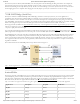
The supply rails downstream are daisy-chained to follow the Xilinx-recommended start-up sequence. Flicking the power switch (SW4) will
enable the 1.0V rail, which enables the 1.8V digital supply rail, which in turn enables the I/O supply rails 3.3V and 1.35V. The 1.25V
reference and 1.8V analog supply ramp together with the 3.3V rail. Once all the channels of the ADP5052 (IC25) supply reach regulation,
the PGOOD signal will assert, enabling the 3.3V audio supply, lighting up the power LED () (LD13), and de-asserting the Power-On Reset
signal (PS_POR_B) of the Zynq.
Each power supply uses a soft-start ramp of 1-10ms to limit in-rush current. There is an additional delay of at least 130ms after the power
rails reach regulation and before the Power-On Reset signal de-assert to allow for the PS_CLK (IC22) to stabilize.
The current being consumed by the Zybo Z7 from the power input can be monitored using the IMON signal of the TPS25940 eFuse device
(IC26). The voltage on the IMON signal is directly proportional to the current being consumed, and is connected to the dedicated analog
input pair on the Zynq-7000 (V_P/V_N) so it can be measured using the internal ADC () (called the XADC core). For information on how
to use the XADC core, please see section “16.3 Dual Analog/Digital Pmod (XADC Pmod)”. It is recommended that 256 averaging mode
be used for more accurate results.
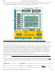
1.2 Power Specifications
1.3 Power Sequencing
1.4 Current Monitoring