
Data Sheet


2/10/2018 Zybo Z7 Reference Manual [Reference.Digilentinc]
https://reference.digilentinc.com/reference/programmable-logic/zybo-z7/reference-manual 14/33
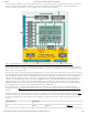
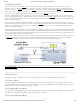
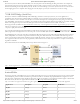
The Zybo Z7 power circuitry was carefully designed to meet the requirements of the Zynq-7000 and all other peripherals while also
providing flexible input supply options. An overview of the power circuit is shown in Figure 1.1.
(https://reference.digilentinc.com/_detail/reference/programmable-logic/zybo-z7/zybo-z7-power.png?id=reference%3Aprogrammable-logic%3Azybo-
z7%3Areference-manual)
Figure 1.1. Power circuit overview
All on-board power supplies are enabled or disabled by the power switch (SW4). The power indicator LED () (LD13, labeled PGOOD) is
on when all the supply rails reach their nominal voltage.
The Zybo Z7 can be powered from several different sources. Jumper JP6 (near the power switch) determines which power source is used.
There are three valid configurations for this jumper corresponding to the three powering options: USB, wall wart supply with barrel jack,
and battery pack. Figure 1.1 depicts all three, and a diagram on the board silkscreen does as well.
The recommended power source is an external power supply (such as a wall-wart) with a barrel jack connector (also known as a coaxial
power connector). The supply must use a center-positive 2.1mm internal-diameter plug and deliver between 4.5V to 5.5V DC. It should also
be able to output at least 2.5 A (12.5 Watts) in order to support power hungry Zynq projects and external peripherals. To use an external
supply with a barrel jack, plug it into the power jack (J17), set jumper JP6 to “WALL”, and then set SW4 to “ON”. Suitable supplies can be
purchased from the Digilent website or Digilent distributors, as well as popular electronics vendors.
An external power source, such as a battery pack, that does not have a suitable barrel jack connector can still be used by wiring it’s positive
terminal to the center pin of JP6 and the negative terminal to the pin labeled J16 next to JP6. The external supply must still meet the same
voltage and current requirements as a supply attached to the barrel jack.
It is also possible to power the Zybo Z7 from the USB programming port (J12), however the Zybo Z7 often requires more current than the
0.5 A of current that is allowed by a USB 2.0 device. If this limit is exceeded, many USB hosts will begin to droop the voltage briefly until
the Zybo Z7 resets, dropping current consumption into acceptable ranges. To help prevent this, a USB host port should be chosen that can
support higher current (often referred to as a “fast charging USB port” or similar by laptop/PC vendors). Many USB battery packs and wall
supplies will also support higher current draws. Even when attached to a host capable of providing more current, the Zybo Z7 will limit
itself to .75 A, and will reset if this current is reached. If you experience your project resetting (indicated by a brief flicker on the PGOOD
LED () and the DONE LED () turning off) while powered from a high current USB port, you will either need to lower the power
consumption of your project or use an external power source.
For reference, we found that the out of box demo loaded on the Zybo Z7 at the factory consumes about 0.5 A from the input power
source. More demanding applications, including any that drive multiple peripheral boards or other USB devices, will likely draw more.
The Zybo Z7 has over-voltage protection up to 20 V on all power inputs that will kick in when a voltage of greater than 5.7 V is detected on
the selected input. It will also limit current draw to .75 A when powered from USB and 4 A when powered from an external source. This
protection is implemented using a Texas Instruments TPS25940 eFuse, please refer to its datasheet for further specifications.
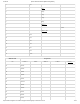
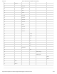
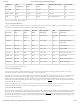
Table 1.1.1 provides an overview of the power input specifications for the Zybo Z7.
Functional Description
1 Power Supplies
1.1 Power Input Sources