
Instruction Manual

PmodGYRO2 Reference Manual
www.digilentinc.com page 2 of 2
Copyright Digilent, Inc. All rights reserved. Other product and company names mentioned may be trademarks of their respective owners.
temporary spikes in data from causing a failing
status response by filtering raw data from the
self-test before sending a pass/fail status. The
module stores both the raw data and the
filtered data in the HICSTx and LOCSTx
registers. Users may access this data should
they be concerned about these energy spikes.
The temperature sensor data is useful for
temperature compensation of the rate data and
is also directly available to the user. To get the
temperature sensor data users must simply
execute a read command of the TEMx
registers from the device.
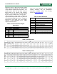
Table 1: Interface Connector Signal
Description
Note: For more information on the GYRO2
module interface, see the ADXRS453
datasheet available online from Analog
Devices at www.analog.com.
Table 2: SPI Bit Definitions
Bits
Description
SQ[2:0] Sequence bits
SM[2:0] Sensor module bits (always 0b000)
A[8:0] Register address
D[15:0] Data
P Command odd parity
SPI SPI command/response error
RE Request Error
DU Data Unavailable
ST[1:0] Status Bits
P0 Response, odd parity, Bits[31:16]
P1 Response, odd parity, Bits[31:0]
Table 3: SPI Commands
Table 4: SPI Responses
Connector J1
Pin
Signal
Description
1 CS Chip Select
2 MOSI Master Out/Slave In
3 MISO Master In/Slave Out
4 SCLK Serial Clock
5 GND Power Supply Ground
6 VCC Power Supply (3.3v)