
Data Sheet

MaxBotix
®
Inc.
Copyright 2005 - 2015 MaxBotix Incorporated
Patent 7,679,996
LV-MaxSonar
®
-
EZ™
Series
Page 2
Web: www.maxbotix.com
PD11832f
MaxBotix Inc., products are engineered and assembled in the USA.
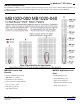
About Ultrasonic Sensors
Our ultrasonic sensors are in air, non-contact object detection and ranging sensors that detect objects within an area. These
sensors are not affected by the color or other visual characteristics of the detected object. Ultrasonic sensors use high
frequency sound to detect and localize objects in a variety of environments. Ultrasonic sensors measure the time of flight
for sound that has been transmitted to and reflected back from nearby objects. Based upon the time of flight, the sensor
then outputs a range reading.
_______________________________________________________________________________________________________________________________________
Pin Out Description
Pin 1-BW-*Leave open or hold low for serial output on the TX output. When BW pin is held high the TX output sends a
pulse (instead of serial data), suitable for low noise chaining.
Pin 2-PW- This pin outputs a pulse width representation of range. The distance can be calculated using the scale factor of
147uS per inch.
Pin 3-AN- Outputs analog voltage with a scaling factor of (Vcc/512) per inch. A supply of 5V yields ~9.8mV/in. and
3.3V yields ~6.4mV/in. The output is buffered and corresponds to the most recent range data.
Pin 4-RX– This pin is internally pulled high. The LV-MaxSonar-EZ will continually measure range and output if RX
data is left unconnected or held high. If held low the sensor will stop ranging. Bring high for 20uS or more to
command a range reading.
Pin 5-TX- When the *BW is open or held low, the TX output delivers asynchronous serial with an RS232 format, except
voltages are 0-Vcc. The output is an ASCII capital “R”, followed by three ASCII character digits representing the
range in inches up to a maximum of 255, followed by a carriage return (ASCII 13). The baud rate is 9600, 8 bits, no
parity, with one stop bit. Although the voltage of 0-Vcc is outside the RS232 standard, most RS232 devices have
sufficient margin to read 0-Vcc serial data. If standard voltage level RS232 is desired, invert, and connect an RS232
converter such as a MAX232. When BW pin is held high the TX output sends a single pulse, suitable for low noise
chaining. (no serial data)
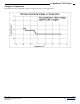
Pin 6-+5V- Vcc – Operates on 2.5V - 5.5V. Recommended current capability of 3mA for 5V, and 2mA for 3V. Please
reference page 4 for minimum operating voltage verses temperature information.
Pin 7-GND- Return for the DC power supply. GND (& Vcc) must be ripple and noise free for best operation.
_______________________________________________________________________________________________________________________________________
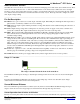
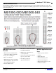
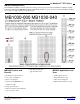
Range “0” Location
The LV-MaxSonar-EZ reports the range to distant targets starting from the front of the sensor as shown in the diagram
below.
In general, the LV-MaxSonar-EZ will report the range to the leading edge of the closest detectable object. Target
detection has been characterized in the sensor beam patterns.
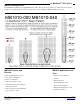
Sensor Minimum Distance
The sensor minimum reported distance is 6-inches (15.2 cm). However, the LV-MaxSonar-EZ will range and report
targets to the front sensor face. Large targets closer than 6-inches will typically range as 6-inches.
_______________________________________________________________________________________________________________________________________
Sensor Operation from 6-inches to 20-inches
Because of acoustic phase effects in the near field, objects between 6-inches and 20-inches may experience acoustic phase
The range is measured from the front of the transducer.
Range Zero