
Data Sheet


PmodISNS20™ Reference Manual
Copyright Digilent, Inc. All rights reserved.
Other product and company names mentioned may be trademarks of their respective owners.
Page 3 of 3
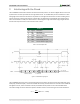
The scaling value at the beginning of the equation was derived using the provided sensitivity of 66mV/A off of the
ACS722 datasheet. Note that the provided sensitivity is based on a reference voltage of 3.3V to the sensor and our
design provides a regulated 3.0V for a cleaner signal, so some more correction may be needed if absolute accuracy
is needed.
Table 2 below shows how to configure the sampling rate frequency. The current sensing chip allows either 20 kHz
or 80 kHz sampling rate which is configured with Jumper 2. Enabling Jumper 1 turns on an analog filter to bring it
down to 120 Hz. The lower frequency is useful to keep noise down on <120 Hz AC circuit applications, such as
reading from mains power.
Rate
JP1
JP2
120 Hz
Enabled
Enabled
120 Hz
Enabled
Disabled
20 kHz
Disabled
Enabled
80 kHz
Disabled
Disabled
Table 2. Sample rate frequency configuration.
In order to read the amperage flowing through the ISNS20, the power source will need to be wired in series
through the green terminal block, noting proper polarity indicated by the silkscreen on the PCB. When using the
ISNS20 for measuring Alternating Current (such as from mains), absolute care should be taken. Improper use of the
ISNS20 on mains power can result in fire, injury, and even death – extreme caution should be taken.
Any external power applied to the PmodISNS20 must be within 3.0V and 3.6V; however, it is recommended that
Pmod is operated at 3.3V.
3 Physical Dimensions
The pins on the pin header are spaced 100 mil apart. The PCB is 1.3 inches long on the sides parallel to the pins on
the pin header and 0.8 inches long on the sides perpendicular to the pin header.