
Data Sheet

Pmod CMPS2™ Reference Manual
Copyright Digilent, Inc. All rights reserved.
Other product and company names mentioned may be trademarks of their respective owners.
Page 5 of 12
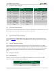
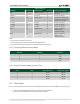
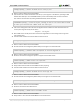
Internal Control 1
Bit Name
Bit Number
Bit Description
Bit Values
Functional Description
RST
[7]
Software reset bit
0¹
Normal Operation, this bit
self clears
TEMP-tst
[6]
Temp test
0¹
Factory-use register
ST_XYZ
[5]
Selftest check
0¹
Set this bit an execute TM
command, the result can be
read as bit ST-XYZ_OK
Z-inhibit
[4]
Z-inhibit
0¹
Factory-use register
Y-inhibit
[3]
Y-inhibit
0¹
Factory-use register
X-inhibit
[2]
X-inhibit
0¹
Factory-use register
BW1³
[1]
Bandwidth bit
0¹
Controls the output
resolution and
measurement time
BW0³
[0]
Bandwidth bit
0¹
Controls the output
resolution and
measurement time
Notes:
¹ - This is the value on power-up and reset
² - For more details see the Continuous Measurement Mode section
³ - For more details see the Output Resolution and Measurement Time section
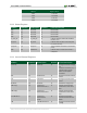
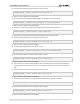
2.2.4 Continuous Measurement Mode
Continuous Measurement Mode Settings
CM Freq1
CM Freq0
Frequency
0
0
1.5 Hz
0
1
13 Hz
1
0
25 Hz
1
1
50 Hz
2.2.5 Output Resolution Measurement Time
Bandwidth Output Resolution and Measurement Time
BW1
BW0
Output Resolution
Measurement Time
0
0
16 bits
7.92 mS
0
1
16 bits
4.08 mS
1
0
14 bits
2.16 mS
1
1
12 bits
1.20 mS
2.3 Quick Start
Here is the series of commands to acquire a set of magnetometer data from the Pmod CMPS2 via pseudo I²C code.
1. Power on the Pmod CMPS2 and wait for 10 mS before further operation.
2. Provide a START condition and call the device ID with a write bit