
Data Sheet

Pmod CMPS2™ Reference Manual
Copyright Digilent, Inc. All rights reserved.
Other product and company names mentioned may be trademarks of their respective owners.
Page 4 of 12
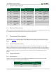
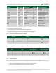
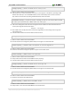
Data Registers addresses 0x00 to 0x05
Address
Register Name
0x02
Y out LSB
0x03
Y out MSB
0x04
Z out LSB
0x05
Z out MSB
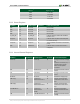
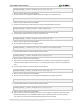
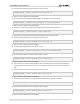
2.2.2 Status Register
Bit Name
Bit Number
Bit Description
Bit Values
Functional Description
RSV
[7]
Reserved
0¹
Reserved Bit
RSV
[6]
Reserved
0¹
Reserved Bit
RSV
[5]
Reserved
0¹
Reserved Bit
RSV
[4]
Reserved
0¹
Reserved Bit
ST_XYZ_OK
[3]
ST_XYZ_OK
0¹
Indicates that the selftest was OK when
this bit is a "1"
Rd_Done
[2]
Rd_Done
0¹
Indicates that chip was successfully able
to read its memory.
Pump On
[1]
Pump On
0¹
This bit indicates the status of the charge
pump.
RSV
[0]
Meas Done
0¹
Indicates that a measurement event is
completed.
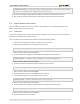
2.2.3 Internal Control Registers
Internal Control 0
Bit Name
Bit Number
Bit Description
Bit Values
Functional Description
Refill Cap
[7]
Refill Cap
0¹
Setting this bit will recharge
the
capacitor at the CAP pin, it is
requested to be issued
before the SET/RESET
command
RST
[6]
Reset Sensor
0¹
Setting this bit will reset the
sensor
SET
[5]
Set Sensor
0¹
Setting this bit will set the
sensor
No Boost
[4]
No boost
0¹
Disable the charge pump
CM Freq1²
[3]
Continuous
Measurement bit 1
0¹
Controls the continuous
measurement rate of the
chip
CM Freq0²
[2]
Continuous
Measurement bit 0
0¹
Controls the continuous
measurement rate of the
chip
Cont Mode On
[1]
Continuous
Measurement
Mode
0¹
Setting this bit enables
Continuous Measurement
Mode
TM
[0]
Take Measurement
0¹
Setting this bit will initiate a
reading