
Data Sheet

2/10/2018 OpenScope MZ Reference Manual [Reference.Digilentinc]
https://reference.digilentinc.com/reference/instrumentation/openscope-mz/reference-manual 17/20
(https://reference.digilentinc.com/_detail/reference/instrumentation/openscope-mz/user_interface_communications.png?
id=reference%3Ainstrumentation%3Aopenscope-mz%3Areference-manual)
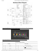
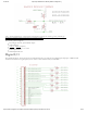
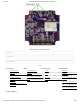
OpenScope MZ uses an FTdI FT232RQ USB/Serial converter to handle the flow control between a host computer and a connected
OpenScope MZ. The host computer will need a USB 2.0 High Speed (or better) port to allow the OpenScope MZ to run at 1.25 MBaud
(139 kB/s) and to negotiate 500 mA on the USB bus. Users may interact with the OpenScope MZ via a terminal in either Menu Mode or
JSON Mode. A pair of DMA channels at the lowest priority are dedicated to the UART. If any other DMA channels stall out the UART
DMA, all communication with the host will cease.
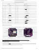
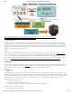
The OpenScope MZ uses a MRF24WG0MA WiFi chip to enable wireless communication with a browser based UI, WaveFormsLive
(https://reference.digilentinc.com/reference/software/waveforms-live/start) (WFL). The OpenScope MZ itself implements a simple HTTP Server
that stores static web content on a μSD card and supports dynamic content implemented in the code through the Digilent deIP™ Network
Stack. More information about WFL and the Digilent Agent (https://reference.digilentinc.com/reference/software/digilent-agent/start) can be
found on the OpenScope MZ Resource Center (https://reference.digilentinc.com/reference/instrumentation/openscope-mz/start).
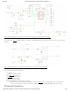
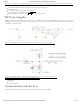
8 out of 9 timers available on the PIC32MZ are utilized for the OpenScope MZ to trigger the ADCs, DMA transfers, PWM outputs, and
trigger delays. Two timers are dedicated to the ADC () channels, two are dedicated to the DC outputs, one for the DC offset, one for the
function generator and logic analyzer, one for an external trigger, and one for the hardware protocol.
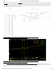
The PIC32MZ triggers are used to initiate and control all of the DMA transfers in the OpenScope MZ. When a trigger is enabled, a data
acquisition will run continuously before the trigger event because it is not known when the trigger event will occur. Data acquisition will also
continue to run until all post trigger data is collected. Due to data acquisition size limitations, it is not possible to measure a point of interest
that exists too far in advance prior to the trigger event. The reverse for a point of interest too far after a trigger event is also true.
Supported triggers for the oscilloscope are:
Rising or Falling Edge triggers
Rise/Fall time with lower and upper threshold
By default WaveForms Live sets the lower threshold 30 mV below the upper threshold
Supported triggers for the logic analyzer are:
Rising, Falling or either Edge triggers
UART Interface
WiFi
Timers
Triggers