
Data Sheet

2/10/2018 OpenScope MZ Reference Manual [Reference.Digilentinc]
https://reference.digilentinc.com/reference/instrumentation/openscope-mz/reference-manual 12/20
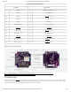
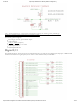
OpenScope MZ J1 Header Pinout
Top Row Bottom Row
7 D5 (5) 8 SDI/SDO/UART_TX (P2)
9 D4 (4) 10 SDI/SDO (P1)
11 D3 (3) 12 INT ()/CLK2 (C2)
13 D2 (2) 14 DO10 (10)
15 D1 (1) 16 DO9 (9)
17 Trigger Input (T1) 18 Trigger Output (T0)
19 GND () (↓) 20 GND () (↓)
21 AWG1 (W1) 22 INT ()/CLK1 (C1)
23 DC Output 1 (V1) 24 DC Output 2 (V2)
25 GND () (↓) 26 GND () (↓)
27 AI2+/OSC2 (2+) 28 GND ()/AI2- (2-)
29 AI1+/OSC1 (1+) 30 GND ()/AI1- (1-)
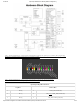
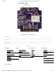
(https://reference.digilentinc.com/_detail/reference/instrumentation/openscope-mz/openscopemz_walk_around.png?
id=reference%3Ainstrumentation%3Aopenscope-mz%3Areference-manual)
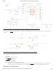
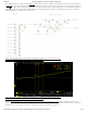
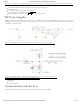
OpenScope MZ uses the ADC () on the PIC32MZ to create a 2 channel oscilloscope with 12-bits of resolution per channel. Each channel
has a pair of analog inputs with a PWM output to facilitate the interleaving of the two inputs, one PWM to handle the input offset voltages,
and one DMA channel at the second highest priority to transfer the measured data.
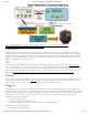
Walk Around the Board
Oscilloscope