
Data Sheet

Nexys Video™ FPGA Board Reference Manual
Copyright Digilent, Inc. All rights reserved.
Other product and company names mentioned may be trademarks of their respective owners.
Page 9 of 29
to work, the bitstream needs to be generated with the x4 bus width option (Vivado device property) and the non-
volatile quad configuration bit in the flash needs to be enabled. The Nexys Video is shipped with this bit enabled.
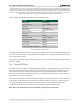
Indirect programming of the flash can also be done using the iMPACT tool included with ISE. The correct part to be
set in the tools is s25fl256xxxxxx0 from the manufacturer Spansion®.
The Nexys Video Programming Guide, which is available on the Nexys Video Resource Center, walks through the
process of programming the Quad-SPI flash from Vivado.
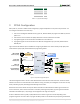
2.3 USB Host and MicroSD Programming
You can program the FPGA from a pen drive attached to the USB-HID port (J15) or a microSD card inserted into J3
by doing the following:
1. Format the storage device (pen drive or microSD card) with a FAT32 file system.
2. Place a single .bit configuration file in the root directory of the storage device.
3. Attach the storage device to the Nexys Video.
4. Set the JP4 Programming Mode jumper on the Nexys Video to "USB/SD".
5. Select the desired storage device using JP3.
6. Push the PROG button or power-cycle the Nexys Video.
The FPGA will automatically configure with the .bit file on the selected storage device. Any .bit files that are not
built for the proper Artix-7 device will be rejected by the FPGA.
The Auxiliary Function Status, or "BUSY" LED (LD14), gives visual feedback on the state of the configuration process
when the FPGA is not yet programmed:
When steadily lit, the auxiliary microcontroller is either booting up or currently reading the configuration
medium (microSD or pen drive) and downloading a bitstream to the FPGA.
A slow pulse means the microcontroller is waiting for a configuration medium to be plugged in.
In case of an error during configuration, the LED will blink rapidly. This could mean that the device
plugged in is not recognized, it is not properly formatted, or the bitstream is not compatible with the
FPGA.
When the FPGA has been successfully configured, the behavior of the LED is application-specific. For example, if a
USB keyboard is plugged in, a rapid short blink will signal the receipt of an HID input report from the keyboard.
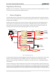
3 Memory
The Nexys Video board contains two external memories: a 512MiByte volatile DDR3 memory and a 32MiByte non-
volatile Serial Flash device. The DDR3 uses a 16-bit wide memory component soldered on the board with industry-
standard interface. The Serial Flash is on a dedicated quad-mode (x4) SPI bus.
3.1 DDR3
The Nexys Video includes one Micron MT41K256M16HA-187E DDR3 memory component creating a single rank,
16-bit wide interface. It is routed to a 1.5V-powered high range (HR) FPGA bank with 50 ohm controlled single-
ended trace impedance. 50 ohm internal terminations in the FPGA are used to match the trace characteristics.
Similarly, on the memory side, on-die terminations (ODT) are used for impedance matching.