
Data Sheet

Nexys Video™ FPGA Board Reference Manual
Copyright Digilent, Inc. All rights reserved.
Other product and company names mentioned may be trademarks of their respective owners.
Page 19 of 29
Artix-7
M18
M17
P17
M13
R15
R17
T18
U18
P18
R13
BTNL
BTNR
BTNU
BTND
SW0
SW1
SW2
SW3
SW4
SW5
SW6
SW7
VADJ
LD0
LD1
LD2
LD3
LD4
LD5
LD6
LD7
LEDs
L16
J15
H17
K15
J13
N14
R18
V17
U17
U16
Slide
Switches
VADJ
Buttons
N17
BTNC
BTN6
1.5V
CPU Reset
C12
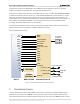
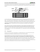
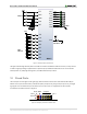
Figure 11. General purpose I/O connections.
The eight individual high-efficiency LEDs are anode-connected to the FPGA via 100-ohm resistors, so they will turn
on when a logic high voltage is applied to their respective I/O pin. Additional LEDs that are not user-accessible
indicate power-on, FPGA programming status, and USB and Ethernet port status.
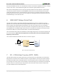
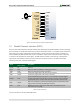
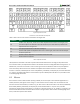
10 Pmod Ports
The Pmod ports are arranged in a 2x6 right-angle, 100-mil female connectors that mate with standard 2x6 pin
headers. Each 12-pin Pmod connector provides two power pins (6 and 12), two ground pins (5 and 11), and eight
logic signals. The VCC and Ground pins can deliver up to 1A of current. Pin assignments for the Pmod I/O
connected to the FPGA are shown in Figure 12.
Pin 1
Pin 12
Pin 6
8 signalsVCC GND
Figure 12. Pmod ports: front view as loaded on PCB.