
Data Sheet

Nexys Video™ FPGA Board Reference Manual
Copyright Digilent, Inc. All rights reserved.
Other product and company names mentioned may be trademarks of their respective owners.
Page 18 of 29
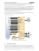
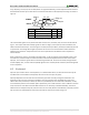
The mouse assumes a relative coordinate system wherein moving the mouse to the right generates a positive
number in the X field, and moving to the left generates a negative number. Likewise, moving the mouse up
generates a positive number in the Y field, and moving down represents a negative number (the XS and YS bits in
the status byte are the sign bits – a '1' indicates a negative number). The magnitude of the X and Y numbers
represent the rate of mouse movement: the larger the number, the faster the mouse is moving (the XV and YV bits
in the status byte are movement overflow indicators – a '1' means overflow has occurred). If the mouse moves
continuously, the 33-bit transmissions are repeated every 50ms or so. The L and R fields in the status byte indicate
Left and Right button presses (a '1' indicates the button is being pressed).
L R 0 1 XS YS XY YY P X0 X1 X2 X3 X4 X5 X6 X7 P Y0 Y1 Y2 Y3 Y4 Y5 Y6 Y7 P1 0 1 00 11
Idle state
Start bit
Mouse status byte X direction byte Y direction byte
Stop bit Start bit
Stop bit
Idle state
Stop bit Start bit
Figure 10. Mouse data format.
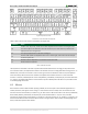
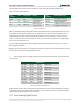
The microcontroller also supports Microsoft® IntelliMouse®-type extensions for reporting back a third axis representing the mouse wheel, as
representing the mouse wheel, as shown in
Table 8.
Command
Action
EA
Set stream mode. The mouse responds with "acknowledge" (0xFA) then resets its movement
counters and enters stream mode.
F4
Enable data reporting. The mouse responds with "acknowledge" (0xFA) then enables data
reporting and resets its movement counters. This command only affects behavior in stream
mode. Once issued, mouse movement will automatically generate a data packet.
F5
Disable data reporting. The mouse responds with "acknowledge" (0xFA) then disables data
reporting and resets its movement counters.
F3
Set mouse sample rate. The mouse responds with "acknowledge" (0xFA) then reads one more
byte from the host. This byte is then saved as the new sample rate, and a new "acknowledge"
packet is issued.
FE
Resend. FE directs mouse to re-send last packet.
FF
Reset. The mouse responds with "acknowledge" (0xFA) then enters reset mode.
Table 8. Microsoft IntelliMouse-type extensions, commands, and actions.
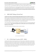
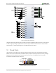
9 Basic I/O
The Nexys Video board includes eight slide switches, five push buttons, and eight individual LEDs. The pushbuttons
and slide switches are connected to the FPGA via series resistors to prevent damage from inadvertent short circuits
(a short circuit could occur if an FPGA pin assigned to a pushbutton or slide switch was inadvertently defined as an
output). The five pushbuttons arranged in a plus-sign configuration are "momentary" switches that normally
generate a low output when they are at rest, and a high output only when they are pressed. The red pushbutton
labeled "CPU RESET," on the other hand, generates a high output when at rest and a low output when pressed.
The CPU RESET button is intended to be used in processor designs to reset the processor, but you can also use it as
a general purpose pushbutton. Slide switches generate constant high or low inputs depending on their position.