
Data Sheet

Nexys Video™ FPGA Board Reference Manual
Copyright Digilent, Inc. All rights reserved.
Other product and company names mentioned may be trademarks of their respective owners.
Page 16 of 29
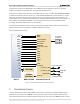
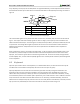
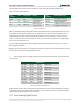
first), odd parity, and stop bit, but the data packets are organized differently, and the keyboard interface allows bi-
directional data transfers (so the host device can illuminate state LEDs on the keyboard). Bus timings are shown in
Figure 8.
T
CK
T
SU
Clock time
Data-to-clock setup time
30us
5us
50us
25us
Symbol Parameter Min Max
T
HLD
Clock-to-data hold time 5us 25us
Edge 0
‘0’ start bit
‘1’ stop bit
Edge 10
Tsu
Thld
Tck Tck
CLOCK
DATA
Figure 8. PS/2 device-to-host timing diagram.
The clock and data signals are only driven when data transfers occur; otherwise, they are held in the idle state at
logic '1'. This requires that when the PS/2 signals are used in a design, internal pull-ups must be enabled in the
FPGA on the data and clock pins. The clock signal is normally driven by the device, but may be held low by the host
in special cases. The timings define signal requirements for mouse-to-host communications and bi-directional
keyboard communications. A PS/2 interface circuit can be implemented in the FPGA to create a keyboard or
mouse interface.
When a keyboard or mouse is connected to the Nexys Video, a "self-test passed" command (0xAA) is sent to the
host. After this, commands may be issued to the device. Since both the keyboard and the mouse use the same
PS/2 port, one can tell the type of device connected using the device ID. This ID can be read by issuing a Read ID
command (0xF2). Also, a mouse sends its ID (0x00) right after the "self-test passed" command, which distinguishes
it from a keyboard.
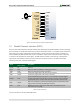
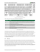
8.2 Keyboard
PS/2 uses open-collector drivers so the keyboard, or an attached host device, can drive the two-wire bus (if the
host device will not send data to the keyboard, then the host can use input-only ports).
PS/2-style keyboards use scan codes to communicate key press data. Each key is assigned a code that is sent
whenever the key is pressed. If the key is held down, the scan code will be sent repeatedly about once every
100ms. When a key is released, an F0 key-up code is sent, followed by the scan code of the released key. If a key
can be shifted to produce a new character (like a capital letter), then a shift character is sent in addition to the scan
code, and the host must determine which ASCII character to use. Some keys, called extended keys, send an E0
ahead of the scan code (and they may send more than one scan code). When an extended key is released, an E0 F0
key-up code is sent, followed by the scan code. Scan codes for most keys are shown in Figure 9.