
Data Sheet

Nexys Video™ FPGA Board Reference Manual
Copyright Digilent, Inc. All rights reserved.
Other product and company names mentioned may be trademarks of their respective owners.
Page 13 of 29
driven by the 100 MHz input clock. For a full description of these rules and of the capabilities of the Artix-7 clocking
resources, refer to the "7-Series FPGAs Clocking Resources User Guide" (ug472) available from Xilinx.
Xilinx offers the Clocking Wizard IP core to help users generate the different clocks required for a specific design.
This wizard will properly instantiate the needed MMCMs and PLLs based on the desired frequencies and phase
relationships specified by the user. The wizard will then output an easy-to-use wrapper component around these
clocking resources that can be inserted into the user's design. The clocking wizard can be accessed from within the
Vivado Block Design or Core Generator tools.
6 USB UART Bridge (Serial Port)
The Nexys Video includes an FTDI FT232R USB-UART bridge (attached to connector J13) that lets you use PC
applications to communicate with the board using standard Windows COM port commands. Free USB-COM port
drivers, available from Windows Update or www.ftdichip.com under the "Virtual Com Port" or VCP heading,
convert USB packets to UART/serial port data. Serial port data is exchanged with the FPGA using a two-wire serial
port (TXD/RXD) with no handshake signals. After the drivers are installed, I/O commands can be used from the PC
directed to the COM port to produce serial data traffic on the V18 and AA19 FPGA pins.
Two on-board status LEDs provide visual feedback on traffic flowing through the port: the transmit LED (LD13) and
the receive LED (LD12). Signal names that imply direction are from the point-of-view of the DTE (Data Terminal
Equipment), in this case the PC.
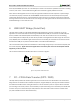
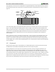
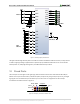
The connections between the FT232R and the Artix-7 are shown in Figure 5.
TXD V18
Micro-USB
(J13)
2
RXD
Artix-7FT232R
AA19
Figure 5. Nexys Video FT232R connections.
7 PC – FPGA Data Transfer (DPTI / DSPI)
The Nexys Video provides two interface types that can be used to transfer user data between a PC and an FPGA
design. Both of the interfaces have a software component, a Digilent Adept API, and a physical interface between
the FPGA and the USB controller. Calling API functions on the PC will either present or request data on the FPGA
pins according to the chosen protocol. The functionality is implemented using the on-board dual-port FT2232 USB
controller. One port is used exclusively for JTAG, while the other either DPTI or DSPI. Since the interfaces share
pins, DPTI and DSPI cannot be used simultaneously.