
Data Sheet

Nexys Video™ FPGA Board Reference Manual
Copyright Digilent, Inc. All rights reserved.
Other product and company names mentioned may be trademarks of their respective owners.
Page 11 of 29
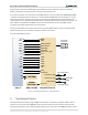
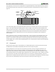
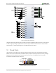
CS#
SDI/DQ0
SDO/DQ1
L12/CCLK
R22
P22
T19
SPI Flash
WP#/DQ2
HLD#/DQ3
P21
R21
SCK
Artix-7
SPI Flash
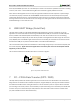
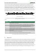
4 Ethernet PHY
The Nexys Video board includes a Realtek RTL8211E-VL PHY paired with an RJ-45 Ethernet jack with integrated
magnetics to implement a 10/100/1000 Ethernet port for network connection. The PHY interfaces with the FPGA
via RGMII for data and MDIO for management. Bank 13 powered at 2.5V is populated with these signals. The
auxiliary interrupt (INT_B) and power management (PME_B) signals are also wired to bank 13. The reset signal
(RST_B) is the only one wired to a different bank (34), powered at 3.3V. The connection diagram can be seen in
Figure 4.
At power-on reset, the PHY is set to the following defaults using the configuration pins in parenthesis:
Auto-negotiation enabled, advertising all 10/100/1000 modes (AN[1:0])
PHY address=00001 (PHY_AD[2:0])
No delay for TXD and RXD relative to TXC and RXC for data latching (RXDLY, TXDLY)
If an Ethernet cable is plugged in, an establishing link is attempted straight after power-up, even if the FPGA is not
programmed.
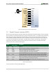
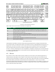
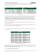
Three status indicator LEDs are on-board near the RJ-45 connector that indicate traffic (LD10) and valid link state
(LD9). Table 4 below shows the default behavior.
Function
Designator
State
Description
ACT
LD10
Blinking
Transmitting or receiving
LINK
LD9
On
Link up
Blinking 0.4s ON, 2s OFF
Link up, Energy Efficient Ethernet (EEE) mode
USER
LD8
On
Link up, no traffic
Off
Link down
Blinking
Link up, traffic
Table 4. Ethernet status LEDs.
The on-board PHY implements Layer 1 in the Ethernet stack, interfacing between the physical copper medium and
the media access control (MAC). The MAC must be implemented in the FPGA and mapped to the PHY's RGMII
interface. Vivado-based designs can use the Xilinx AXI Ethernet Subsystem IP core to implement the MAC and wire
it to the processor and the memory subsystem. At the time of writing, the IP core needed to be licensed separately
Figure 3. Nexys Video SPI Flash pin-out.