
Manual

NetFPGA-SUME™ Reference Manual
Copyright Digilent, Inc. All rights reserved.
Other product and company names mentioned may be trademarks of their respective owners.
Page 18 of 18
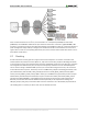
connector provides two 3.3V VCC signals (pins 6 and 12), two Ground signals (pins 5 and 11), and eight logic
signals, as shown below. The VCC and Ground pins can deliver up to 1A of current. Pmod data signals are not
matched pairs, and they are routed using best-available tracks without impedance control or delay matching.
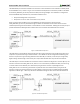
The signals on the Pmod connector are connected to the FPGA via two 4-bit dual-supply bus transceivers (IC1 and
IC2, part number SN74AVC4T774) with configurable voltage translation and 3-state outputs. You need to
specifically set DIR for each pin to control the signal direction. The bus transceiver is enabled by driving OE pin of
the bus transceiver low.
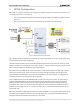
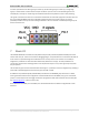
7 Basic I/O
The NetFPGA-SUME board includes two LEDs (LD0 and LD1) and two pushbuttons (BTN0 and BTN1) that can be
used for basic user I/O. These can be useful for debugging designs. The pushbuttons are connected to the FPGA via
series resistors to prevent damage from inadvertent short circuits (a short circuit could occur if an FPGA pin
assigned to a pushbutton or slide switch was inadvertently defined as an output). The two pushbuttons are
"momentary" switches that normally generate a low output when they are at rest, and a high output only when
they are pressed.
The two LEDs are green and are illuminated when driven high. It is possible to control the brightness by providing a
pulse-width modulated signal that varies the duty cycle from 0% to 100%.
An additional red pushbutton (BTN3, labeled PROG) is attached to the PROGRAM_B pin of the Virtex-7 FPGA.
Pressing this button will clear the configuration inside the FPGA and cause the DONE pin to go low. If the mode
jumper is not shorted, this will also trigger the CPLD to reprogram the FPGA with a bitstream stored in flash (See
the "FPGA Configuration" section for more info).
LD4 is attached to the DONE pin of the FPGA, and is illuminated whenever the FPGA is configured with a valid
bitstream.